
Summary of Contents for TKH KEYPROCESSOR Pluto
-
Page 1: About This Publication
Installation instructions Modular controller line • Pluto • Orion Doc. no.: 01052018... -
Page 2: Table Of Contents
About this publication May 2018, Keyprocessor BV Paasheuvelweg 20 1105BJ Amsterdam The Netherlands www.keyprocessor.com Tel.: +31 (0)2 04 62 07 00 This instruction manual is based on knowledge relevant at the above-mentioned date. Keyprocessor is constantly working towards the improvement of its products. For information on the most recent technical state of affairs, please contact your consultant or distributor. - Page 3 7.2.1.2 Wiring requirements ................... 25 7.2.2 Clock- data / Wiegand card reader ............... 25 7.2.2.1 Connecting the card reader ................26 7.2.2.2 Wiring requirements ................... 26 Bus configuration with card reader ............... 26 7.3.1 Pluto – Orion as starting point of kpBus ............27 7.3.1.1 Connection of kpBus ...................
-
Page 5: List Of Images
List of images Figure 1: Mounting controller ..................7 Figure 2: Tamper contact ....................8 Figure 3: Stacking connector ..................8 Figure 4: Front side Pluto ..................... 10 Figure 5: Rear side Pluto ..................... 10 Figure 6: Example of connection with Orions ..............12 Figure 7: Pluto serial connection .................. -
Page 6: Introduction
1 Introduction This instruction manual covers the entire range of Keyprocessor modular controllers. One or more software versions are specified in every module-related chapter. These versions are important when it comes to support for the product. -
Page 7: General
2 General Mounting Mount on a 35mm DIN rail type O profile. Mount the rail to a wall or inside a secure casing. Place the modular controller against the rail and click it into place. Figure 1: Mounting controller Mounting the modular controller onto the rail. -
Page 8: Power Supply Connection And Tamper Contact
Power supply connection and tamper contact The controller requires a power feed. For this purpose, use an orange four-pole power terminal or the stacking connector. The tamper contact T must be connected to the – GND terminal. SW-1 ─ Figure 2: Tamper contact Connector D The Pluto can be connected to a 12VDC or 24VDC power supply. -
Page 9: Pluto
3 Pluto The Pluto is an extremely powerful controller with a multicore processor, a secure bootloader (u-boot), and a linaro release with Linux kernel. Applications Depending on the situation, the Pluto can be used in a range of different ways. The Pluto can be used if: •... -
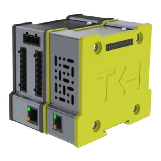
Page 10: Connections
Connections Figure 5: Rear side Pluto Figure 4: Front side Pluto Port Description USB 2.0 port (x2) Stacking connector for Orions Status LED Power input USB OTG console port Network port Stacking terminal (for future use) Status LED With the RGB LED, the current mode of the Pluto can be determined at a single glance. The Pluto’s status LED is described in the table below: Port C Colour of the LED... - Page 11 The maximum numbers are described in the table below: Pluto storage (FIFO) Description: Maximum per Pluto: Cards with valid access rights 50.000 Events 50.000...
-
Page 12: Pluto Connection Options
4 Pluto connection options The Pluto’s various connection options are described in this section. Connecting with Orion The right-hand terminal on the Pluto is not designed for use with a controller. Connecting a modular controller (e.g. an Orion) to the LED side of the Pluto will not damage it, however, communication with the device will not be possible. -
Page 13: Serial Connection (Rs-232)
Serial connection (RS-232) If a connection in series is preferred, a USB-to-RS232 converter (recommended by Keyprocessor, part number 503-1805) must be used. Only one USB-to-RS-232 converter can be used per Pluto (See chapter 14.5). Rear RS-232 Figure 7: Pluto serial connection... -
Page 14: Maintenance
5 Maintenance page Pluto The Pluto has its own maintenance page. This maintenance page includes assistance with network settings as well as system testing. The Pluto’s default IP address is 192.168.1.195. In order to access the maintenance page, enter the following into your browser: https://192.168.1.195 When the page opens, it will display a login screen. - Page 15 Once saved, the new settings will take immediate effect and the Pluto will only be accessible using the new IP address.
-
Page 16: Orion
6 Orion Applications The Orion can be used for a range of applications. Extra features include: • End-to-End security (RS485 card reader) • RS485 communication bus (kpBus) • Replacement of existing Orbit reader • Additional functionality Required software versions In order to guarantee optimum performance, the following software versions are required: Version Supported iProtect... -
Page 17: Orion - Rs485 Bus Communication (Kpbus)
Power measurement reader Power consumption readers H1 and H2 overload detection 6.3.2 Orion – RS485 bus communication (kpBus) Type of controller Polyx, Pluto connected: Number Connection Digital input T1, T2 Digital output O1, O2, O3, O4, O5, O6, H1 and H2 Monitored inputs (ADC) A1, A2, A3, A4, A5, A6 Orion override input... -
Page 18: Connections
Connections The connection ports on the Orion are described in this section. Options depend on the application and the method of connection. PRT2 PRT1 Figure 8: Orion Figure 9: Orion connections front connections rear Port Description PRT1 Reader 1 IO 1 Power input Status LED MicroSD slot... -
Page 19: Description Imprint Orion
6.4.1 Description imprint Orion The connection ports and imprints on the Orion are illustrated below: Figure 10: Imprint Orion rear Figure 11: Imprint Orion front Reader & IO-1 Connector: A Description PRT1 Communication port Connector: B Description Connector: C Description GND (digital ground) Monitored input 1 Digital input (Override card reader) -
Page 20: Status Led
Connector: I Description kpBus (RS485) kpBus (RS485) GND (digital ground), for data use only. kpSensor Reader & IO-2 Connector: J Description Connector: K Description GND (digital ground) Monitored input 4 Digital input (Override card reader) Monitored input 5 Card reader LED operation Monitored input 6 DO/Data or Digital input GND (digital ground) -
Page 21: Sd-Card Functionality
SD-card functionality Additional functionality is available when using an SD card in the Orion. When there is no communication (kpBus) with the network controller, the local operation of the access will be guaranteed. This functionality is available from: • iProtect version 8.04 or higher •... - Page 22 Events Description Push button access Push button no access Card access Card no access Card no calamity card Emergency door release activated Emergency door release deactivated The following table shows all the inputs: Inputs Connection: Description: Reader nr. Invert (NO/NC) Loop (enable) Reader 1 Push button...
-
Page 23: Orion Connection Options
7 Orion connection options The Orion’s various connection options are described in this chapter. Connecting with Orion When it comes to connection, the following conditions are important: • When inserting stacking connectors, always ensure the power is off. • Depending on the power feed being used (at least 24VDC – 75W), a maximum of four Orions can be interconnected to one another by means of stacking connectors. -
Page 24: Connecting Card Reader
Connecting card reader 7.2.1 RS485 card reader Choosing the option to connect RS485 card readers to the controller offers the following advantages: • ‘Key information’ from the card reader is transferred to the controller. The card reader is always publicly accessible, while the controller is located in a secure and concealed area. -
Page 25: Wiring Requirements
7.2.1.2 Wiring requirements The wiring required between the card reader and the Orion is listed below: Cable Communication Remote Communication between protocol UTP ≥Cat5e RS485 120m Orion and Sirius i-series card reader 7.2.2 Clock- data / Wiegand card reader In virtually all configurations, you have the option of connecting a Clock- data / Wiegand card reader to either side of the Orion, except if an RS485 card reader is connected. -
Page 26: Connecting The Card Reader
7.2.2.1 Connecting the card reader Orion reader & TIA/EIA-568-B Sirius i-serie IO-1/2 Description Wire color Sticker Description White/orange Orange White/green Blue White/blue Green White/brown Brown 7.2.2.2 Wiring requirements The wiring required between the card reader and the Orion is listed below: Cable Communication Remote... -
Page 27: Pluto - Orion As Starting Point Of Kpbus
7.3.1 Pluto – Orion as starting point of kpBus If the Orion is linked to the Pluto and the relevant Orion is used as the beginning of a kpBus, then: • The Orion connected to the Pluto is not included in the number of Orions in the kpBus. •... -
Page 28: Connection Of Kpbus
Orion Pluto kpBus A B C Max. 32x Orions Max. 32x card readers PRT1 PRT2 Max. 8 A B C A B C A B C PRT2 PRT2 PRT2 Figure 19: Pluto/Orion - kpBus with Clock- data / Wiegand and RS485 reader 7.3.1.1 Connection of kpBus Orion (I) -
Page 29: Polyx As Communication Starting Point
7.3.2 Polyx as communication starting point Polyx Max. 16x Orions Max. 32x card readers N D 1 2 kpBus-1 Polyx the starting point of kpBus at all times! Max. 8 A B C A B C A B C The last Orion must have an EOL Jumper. -
Page 30: Connection Of Kpbus
7.3.2.1 Connection of kpBus When using shielded cable, one end of the cable’s metal sheath must be attached to the earth ground connection ⏚ in the system cabinet. Polyx TIA/EIA-568-B Orion A B C S PRT1– 2 A B C S Description Wire color White/orange... -
Page 31: Kpsensor Bus Connection
kpSensor bus connection The Orion is fitted with a kpSensor bus port. This allows the Orion to measure, for instance, the temperature and humidity in a certain area. Connector I TIA/EIA-568-B 571-1013 Sensor Colour of the cable Wire color Description White/orange Orange V+ (reader) -
Page 32: Default Inputs And Outputs
Default inputs and outputs The Orion’s inputs and outputs are described below. Reader & IO-1: Symbol Description iProtect default Digital input Door in latch mode D0 / Data or Digital input* D1 / Clock or Digital input* Digital output Monitored input 1 Loop / Enable Monitored input 2 Button... - Page 33 Resistor values DEOL DEOL TEOL TEOL Sabotage inverted inverted 0 – 699 0 – 699 0 – 699 0 – 699 0 – 699 0 – 699 0 – 699 Idle Active Sab. Closed Sab. Closed Sab. Closed Sab. Closed Sab.
-
Page 34: Orion As Replacement For The Orbit Reader
8 Orion as replacement for the Orbit reader As is the case with the Orbit reader, the Orion also supports Clock- Data / Wiegand card readers. In order to use the Orion as a functional replacement for the Orbit reader: •... -
Page 35: Controller <> Orion Prt1 - Rs422
Polyx Polyx Max. 2 Max. 2 Orion RS42 RS422 Orbit 1 Orbit 2 PRT1 PRT1 Clock- Data / Clock- Data / Wiegand Wiegand Figure 25: Polyx with Orbits Figure 26: Polyx with Orions 8.1.1 Controller <> Orion PRT1 - RS422 iPU-8 PRT 1 –... -
Page 36: Default Inputs And Outputs
8.1.3 Default inputs and outputs When replacing an Orbit reader with an Orion, the below table can be used: Orbit 2 Description of Orion iProtect™ Reader 1 connection Reader & IO-1 default +5V 200mA MAX Reader voltage GND (digital ground) D1 / CLK D1 / Clock D0 / DAT... -
Page 37: Pluto-Orion As Replacement For The Ipu-8
9 Pluto-Orion as replacement for the iPU-8 A Pluto in combination with the Orion can serve as a functional replacement unit for the Stellar or ipU-8 Network Controller. When an existing iPU-8 with 8 Orbits installation needs to be replaced, a Pluto with 4 stacked Orions will suffice. -
Page 38: Diagnostics
Diagnostics The Orion can be fully tested before communicating with iProtect ™ through a diagnostic program on the Network Controller. 10.1 Initiating Pluto diagnostics NOTE System diagnostics are only possible if there is no communication between the Pluto and iProtect™. Navigate to the Pluto’s IP address and perform the following steps: •... -
Page 39: Polyx/Ipu-8: Connecting Across The Console Port
10.2 Polyx/iPU-8: Connecting across the Console port System diagnostics can be carried out with the help of a PC / laptop. For the purpose of diagnostics, every Controller has a diagnostics menu. All that is required to do this is a series connection between the Controller and the PC or laptop. However, “Terminal software”... - Page 40 Option 3: Profibus communication test If option 3 - Test Profi device communications - is selected from the main menu of the iPU-8 Diagnostics software, the Profibus DP communication test screen will appear. Here, it is possible to specify per port whether a Profibus device is connected and, if so, which slave it is. Communication mode indicates whether communication has been established (connected/disconnected).
- Page 41 In the menu, an Orion corresponds to an Orbit-2 (Profi DP reader*2). In the following example, option 2, Profi DP reader-2, has been selected: --- Device functionality test --- Enter the device to test 1..8) : 1 1) Profi DP reader-1 2) Profi DP reader-2 3) Profi DP io Enter the device type...
-
Page 42: Initiating Polyx Diagnostics
10.2.2 Initiating Polyx diagnostics Depending on the function and the method of connection (PRT1 or PRT2 from Orion), it is possible to use certain sections of the diagnostics menu. Diagnostics for both connection methods are described in the below paragraphs. 10.2.2.1 Orion as functional replacement for the Orbit reader •... - Page 43 In the following example, option 2, Profi DP reader-2, has been selected: --- Device functionality test --- Enter the device to test 1..8) : 1 1) Profi DP reader-1 2) Profi DP reader-2 3) Profi DP io Enter the device type : Profi DP reader-2 Enter slave no.
-
Page 44: Multiple Orions On A Single Data Line (Bus)
10.2.2.2 Multiple Orions on a single data line (bus) • iPU-8 diagnostics can be accessed by pressing on any key when the following text is displayed: Hit any key within 5s to run diagnostics The main menu will appear, containing the following options Polyx Diags version V3.0.5 1) Environment settings 2) Test onboard I/O... - Page 45 --- Orion test >> snr: 140025, V1.0.20 --- Reader & IO-1 ---------------------------- --------------------- Input A1: off 128 (15939ohm) 1) Output O1: On/Off Input A2: off 128 (15939ohm) 2) Output 02: On/Off Input A3: off 128 (15939ohm) 3) Output O3: On/Off ----- general ---- Input T1: Off 128 4) Output...
-
Page 46: How To
How to 11.1 Installation Pluto Configuring the Pluto: 1. Make sure all connections are in accordance with the technical drawing and connect the Pluto to the network. See chapter 14. 2. Open the Explorer and browse to the following address: https://192.168.1.195. The login screen appears. -
Page 47: New Orion On Existing Pluto
11.2 New Orion on existing Pluto Configuring the Orion: 1. Make sure all connections are in accordance with technical drawing, see chapter 13.2, 13.3 or 14. Configuration in iProtect™: 1. Open menu “Installation” > “Hardware” > “Line” 2. Click on the “Search” button. 3. -
Page 48: New Orion On Existing Polyx
11.4 New Orion on existing Polyx Configuring the Orion: 1. Make sure all connections are in accordance with technical drawing, see chapter 14. Configuration in iProtect™: 1. Open menu “Installation” > “Hardware” > “Line” 2. Click on the “Search” button. 3. -
Page 49: Replace Polyx (2X Kpbus) For Pluto And Two Orions
1. Open menu: “Installation” > “Hardware” > “Line”. 2. Select the correct “Line” which need to be replaced. 3. Under communication select “Active”. 4. Press the button: “Send new KeyStore”. When having the connection between iProtect™ and the Pluto in place, automatically the latest software update will be installed on the Pluto. -
Page 50: Replace Ipu-8 For A Pluto With Four Orions
5. Press the button: “Discover”. Both kpBus lines are converted. 6. Open menu: “General” > “Overviews” > “Last events” and check the operation. 11.7 Replace iPU-8 for a Pluto with four Orions Configuration in iProtect™: 1. Open menu: “Installation” > “Hardware” > “Line”. 2. -
Page 51: Pluto - Removing Iprotect Data
4. Under communication deselect “Active”. 5. Copy the password of the line. 6. Save this record. Configuration in Pluto: 1. Browse to the maintenance page of the Pluto. 2. Login with username “controller” and the line password, generated in iProtect. 3. -
Page 52: Technical Data
Technical data 12.1 Pluto Housing Measurements: 110,0 x 47,0 x 93,0 mm (L x W x H) Weight 0.25 Kg Mounting Dinrail 35mm DIN rail type O profile CPU Name Freescale i.MX6 CPU Type Dual ARM® Cortex™-A9 Core 1.0 GHz Networking Ethernet Gigabit Ethernet Controller, RJ-45 x 1... -
Page 53: Orion
12.2 Orion Housing Measurements: 110.0 x 47.0 x 93mm (L x W x H) Weight: 0,25 Kg Mounting Dinrail 35mm DIN rail type O profile Communication PRT1 Pin out Pin 1 = RXB Pin 5 = GND RJ45 socket, RS422 Pin 2 = RXA Pin 6 = TXB Pin 3 = TXB... - Page 54 Storage temperature & humidity -40 ~ +85°C, 10 ~ 95% RH Polyfuse Type PTC Fuse Case style Thermal derating At -10° C the hold current will increase to 130% At +25° C no derating At +60° C the hold current will reduced to 60% Certifications CE compliant EN 55022:2010...
-
Page 55: Declaration Of Conformity
Declaration of conformity 13.1 Pluto DECLARATION OF CONFORMITY (DoC) Keyprocessor B.V. Paasheuvelweg 20 1105 BJ Amsterdam The Netherlands Declare under our sole responsibility that the product: Pluto Controller The above mentioned product complies with the essential requirements, which are specified in the directive 2014/30/EU on the approximation of the laws of the Member States relating to electromagnetic compatibility. -
Page 56: Orion Controller
13.2 Orion controller DECLARATION OF CONFORMITY (DoC) Keyprocessor B.V. Paasheuvelweg 20 1105 BJ Amsterdam The Netherlands Declare under our sole responsibility that the product: Orion Controller The above mentioned product complies with the essential requirements, which are specified in the directive 2014/30/EU on the approximation of the laws of the Member States relating to electromagnetic compatibility. -
Page 57: Technical Drawings
Technical drawings 14.1 72000310 – Pluto/Orion setup with network connection and power supply... -
Page 58: 72000206 - Pluto/Orion With Sirius Rs485 And Io
14.2 72000206 - Pluto/Orion with Sirius RS485 and IO... -
Page 59: 72000202 - Pluto/Orion With Sirius Clock-Data/Wiegand And I-O
14.3 72000202 - Pluto/Orion with Sirius clock-data/Wiegand and I-O... -
Page 60: 72000207 - Pluto/Orion With Io, Sirius Clock-Data/Wiegand And Orbits
14.4 72000207 – Pluto/Orion with IO, Sirius Clock-data/Wiegand and Orbits... -
Page 61: 72000304 - Pluto With Power Supply And Usb-Rs232 Converter
14.5 72000304 - Pluto with power supply and USB-RS232 converter... -
Page 62: 72000203 - Pluto/Orion With Kpbus
14.6 72000203 – Pluto/Orion with kpBus... -
Page 63: 72000204 - Orion With Kpsensor Bus
14.7 72000204 - Orion with kpSensor bus... -
Page 64: 72000602 - Pluto Orion Stacked With 8X Rs485 Sirius-I Readers
14.8 72000602 - Pluto Orion stacked with 8x RS485 Sirius-i readers... -
Page 65: 72000602 - Pluto Orion With Clock-Data Or Wiegand Readers
14.9 72000602 - Pluto Orion with clock-data or Wiegand readers... -
Page 66: 72000602 - Pluto Orion With Rs485 Readers & Kpbus Combi
14.10 72000602 - Pluto Orion with RS485 readers & kpBus combi... -
Page 67: 72000504 - Polyx With Kpbus
14.11 72000504 - Polyx with kpBus...
Need help?
Do you have a question about the KEYPROCESSOR Pluto and is the answer not in the manual?
Questions and answers