
Summary of Contents for CIS VCC-5CXP3NIR
- Page 1 VCC-5CXP3NIR Rev. 905-0123-00 English CoaXPress I/F 5.3M CMOS Near-Infrared Camera VCC-5CXP3NIR Product Specifications & Operational Manual CIS Corporation ©2018 CIS Corporation. All rights reserved.
-
Page 2: Table Of Contents
9.7 Sequence Status Output ........................28 Factory Settings ............................29 Dimensions ............................. 30 11.1 Optical Axis Accuracy ........................... 30 11.2 Camera Dimensions..........................31 Case for Indemnity (Limited Warranty) ......................32 Product Support ............................32 ©2018 CIS Corporation. All rights reserved. -
Page 3: Handling Precautions
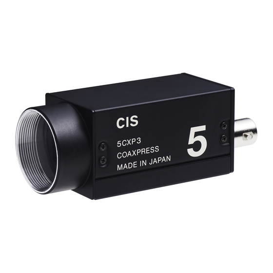
Do not disassemble the camera. The camera once disassembled shall be out of warranty. Product Outline VCC-5CXP3NIR is a CoaXPress interfaced small NIR camera utilizing a 1-inch type, 5.3M pixels CMOS image sensor. Features □ 29mm x 29mm x 55mm in size □... -
Page 4: Specifications
6 directions. (Without packaging) (23) Operation Environment Operation guaranteed: 0 ~ +45℃ Humidity: 20 ~ 80%RH with no condensation (24) Storage Environment Storage Temperature: -25 ~ + 60℃, Hum idity: 20 ~ 80%RH with no condensation. ©2018 CIS Corporation. All rights reserved. -
Page 5: Camera Output Signal Specifications
With register settings, round connector. LVAL, and Uplink Triger 1 can be output. (After decoding). 5V output Spectral Response ※Refer to the data for NIR. The lens characteristic and the illuminant characteristics are excluded. ©2018 CIS Corporation. All rights reserved. -
Page 6: External Connector Pin Assignment
The camera internal timing signals can be output. Please set the signal to be output from Line Source of Digital IO Control. For the details, please refer to the Section 8. ・ 5.0V CMOS logic level output ・ Output voltage Low: 0.55Vdc (Max), High: 3.8Vdc (Min) +5.0V (CAMERA_INTERNAL) SIGNAL_OUT HD74LV1GT32ACME ©2018 CIS Corporation. All rights reserved. -
Page 7: How To Save And Initialize The Settings
ROM. And, the saved settings are reflected when the camera is turned on next time. Camera Operational Mode Link Configuration Transfer Control CXP1_X1 CXP2_X1 CxpLinkConfiguration CXP3_X1 CXP5_X1 CXP6_X1 Pixel Format Settings ImageFormatControl Mono8 PixelFormat Mono10 ©2018 CIS Corporation. All rights reserved. -
Page 8: Camera Sync. Mode
This is a mode to use triggers continuously made in the camera. No external trigger shall be used. Configuration Frame rate (fps) 8bit 10bit CXP-1 21.3 16.3 CXP-2 42.6 34.8 CXP-3 42.6 42.6 CXP-5 85.1 69.5 CXP-6 85.1 85.1 ©2018 CIS Corporation. All rights reserved. -
Page 9: External Trigger Sync. Mode
(exposure for the next frame starts while reading out.). There are some gap of timing between when a trigger is input to the image sensor, and when exposure actually starts. ©2018 CIS Corporation. All rights reserved. - Page 10 Video Out Exposure Out Exposure time Image Image Cxp Stream Idle Stream data Idle Stream data Idle Header Header LVAL FVAL Trigger input forbidden period Readout time Exposure delay time (A) Exposure delay time (B) ©2018 CIS Corporation. All rights reserved.
- Page 11 Effective Line Effective Line Video Out Exposure Out Exposure time Image Image Cxp Stream Idle Stream data Idle Stream data Idle Header Header LVAL FVAL Readout time Exposure delay time (A) Exposure delay time (B) ©2018 CIS Corporation. All rights reserved.
-
Page 12: Camera Function Settings
Preset gain settings are reflected to the manual gain settings. PresetGainX Magnification Converted values Gain_x1 Gain_x1_5 x1.5 3.5dB Gain_x2 Gain_x3 9.5dB Gain_x4 12dB Gain_x6 15.6dB Gain_x8 18dB Gain: Manual gain ・ Any preferred values from x1 to x32 can be set per x0.25. ©2018 CIS Corporation. All rights reserved. -
Page 13: Exposure Time Settings
Pattern7 4750 2370 2370 1160 1160 4750 2370 2370 1160 1160 8Bit 10Bit CXP1 CXP2 CXP3 CXP5 CXP6 CXP1 CXP2 CXP3 CXP5 CXP6 Subsampling 14190 7080 7080 3520 3520 14530 7260 7090 3630 3550 ©2018 CIS Corporation. All rights reserved. -
Page 14: Roi (Region Of Interest)
585.9 585.9 Pattern7 640x480 8bit 199.8 399.5 399.5 799.0 799.0 10bi 183.1 399.5 399.5 799.0 799.0 The following information on the selected ROI area can be read out. ・ ImageFormatControl Width Height OffsetX OffsetY ©2018 CIS Corporation. All rights reserved. - Page 15 VCC-5CXP3NIR Rev. 905-0123-00 ROI area are cut out with the image sensor centered. ・ ©2018 CIS Corporation. All rights reserved.
-
Page 16: Sub-Sampling
277.1 270.4 CXP-6 277.1 277.1 8.5 Image Sensor Defective Pixel Correction CIS compensates the noticeable CMOS pixel defects found at the shipping inspection prior to our shipment. Defective pixel correction can be set to OFF. AnalogControl True DefectivePixelCorrection False ©2018 CIS Corporation. All rights reserved. -
Page 17: Shading Correction
0.25 at 8 bit output, and it changes by approx. 1.0 at 10 bit output. ・ When a lower value than the initial value is set, saturation level would not achieve to the maximum value for output range. ©2018 CIS Corporation. All rights reserved. -
Page 18: Test Pattern
ROI or sub-sampling function was activated while grabbing images. Please reboot the camera, or execute Device Control – SensorReset to revert the camera to normal lighting condition. ©2018 CIS Corporation. All rights reserved. -
Page 19: Camera Timing Output
A user-defined device name can be set in the camera with the maximum of sixteen characters letter string. Execute “UserSetSave” to save the user-defined device name in EEPROM in the camera. Execute “UserDefault” to restore to the factory settings. ※ Register area is 16 byte in total. Please input single-byte alphanumeric characters. ©2018 CIS Corporation. All rights reserved. -
Page 20: Sequence Control Function
SequencerActivation (Start operation) correspond to each sequence mode. AcquisitionControl AquisitionMode [TriggerSelectorAndActivation] SequencerControl 【Sequence operation mode】 【シーケンス動作モード】 [SequencerActivation] Trigger mode トリガーモード FrameStartPredfined ◎ ◎ ◎ ◎ インデックスモード Index mode FrameStartIndexselector ◎ ◎ ◎ ◎ FrameBurstStartEdge Burst mode バーストモード FrameBurstStartLevel ◎ FrameBurstStartSoftware ©2018 CIS Corporation. All rights reserved. -
Page 21: Basic Operation For Sequence Control
At burst mode, the screen will hold the last picture of sequence control when sequence control is completed. ・ Please turn OFF SequencerActivation to return to the condition before sequence control was performed. ・ ©2018 CIS Corporation. All rights reserved. -
Page 22: Trigger Mode And Burst Mode Operational Outline
Index range to execute 各Indexを繰り返す回数 Repeating count for each index Parameter Index Number Sequencer Loop Count SequencerLoopCount ParameterIndexNumber Combination of each Index and parameter set 0: 無限loop, 1~: 有限loop数 各Indexとパラメータセットの紐付け 0: Infinite loop 1~: Limited loop ©2018 CIS Corporation. All rights reserved. -
Page 23: Trigger Mode
Sequence starts with a trigger input when TriggerSelectorAndActivation is set to FrameStartLevelHigh or FrameStartLevelLow. Exposure time for each frame (① and ②) is the pulse width of the trigger. ・ When the image output for the sequence loop count is completed, sequence operation ends. ・ ©2018 CIS Corporation. All rights reserved. -
Page 24: Burst Mode
Sequence operation restarts and operates continuously when the trigger input is changed to High level again. ・ When the image output for the sequence loop count is completed, sequence operation ends. ・ (3) Register start Sequence operation starts simultaneously when the SequencerActivation OFF is set to FrameBurstStartSoftware. ©2018 CIS Corporation. All rights reserved. -
Page 25: Index Mode
※ Notes for the issuing timing of IndexSelectorModeIndexNumber command To reflect the specified parameter set surely to the next frame, please issue IndexSelectorModeIndexNumber, wait for the response of ACK, and then input a trigger pulse. ©2018 CIS Corporation. All rights reserved. -
Page 26: Settings For Sequence Control
The Index range to execute 0-15 IndexSelectorModeIndexNumber Index number to be used at index mode 0-15 ParameterIndexNumber Index 0-15 Parameter number for Index 0-15 0-15 IndexLoopCount IndexCount 0-15 Each loop count for Index 0-15 0-1023 ©2018 CIS Corporation. All rights reserved. - Page 27 Indicates the maximum exposure time to be set. SequencerGain Gain (SequencerXSize) Set X size specified with ROI (SequencerYSize) Set Y size specified with ROI (SequencerXStart) Set X coordinate specified with ROI (SequencerYStart) Set Y coordinate specified with ROI ©2018 CIS Corporation. All rights reserved.
-
Page 28: Sequence Status Output
In case of 10bit video output, 2bit of LSB side shall always be "00". pix0 “00” Index number [3:0] “0000” “00” pix1 “00” Repeating number [7:0] “00” pix2 “00” “000000” Repeating number [9:8] “00” pix3 “00” Loop Count [7:0] “00” pix4 “00” “000000” Loop Count [9:8] “00” ©2018 CIS Corporation. All rights reserved. -
Page 29: Factory Settings
The same value as the Index number. Index 0 Count~Index 15 Count All 1 SequencerLoopCount ActiveIndexModeIndexNumber SequencerExposureTime 1000.0 (Selector 0-15) SequencerGain (Selector 0-15) TransportLayer CxpLinkConfiguration CXP_X1 ※ Factory settings are the same values as the one for UserSetDefault command. ©2018 CIS Corporation. All rights reserved. -
Page 30: Dimensions
VCC-5CXP3NIR Rev. 905-0123-00 11. Dimensions 11.1 Optical Axis Accuracy ©2018 CIS Corporation. All rights reserved. -
Page 31: Camera Dimensions
VCC-5CXP3NIR Rev. 905-0123-00 11.2 Camera Dimensions ©2018 CIS Corporation. All rights reserved. -
Page 32: Case For Indemnity (Limited Warranty)
If you use the product properly and discover a defect during the warranty period, and if that was caused by designing or manufacturing, CIS Corporation, at its option, repairs or replaces it at no charge to you. Products out of warranty period will be subject to charge. CIS repairs the products as long as it is repairable.
Need help?
Do you have a question about the VCC-5CXP3NIR and is the answer not in the manual?
Questions and answers