Table of Contents
Advertisement
Quick Links
Advertisement
Table of Contents

Subscribe to Our Youtube Channel
Summary of Contents for 2N Telekomunikace 2N Access Unit 916009
- Page 1 ® Access Unit Access Control Installation Manual Version www.2n.cz ...
- Page 2 The 2N TELEKOMUNIKACE a.s. is the holder of the ISO 9001:2009 certificate. All development, production and distribution processes of the company are managed by this standard and guarantee a high quality, technical level and professional aspect of all our products.
-
Page 3: Table Of Contents
Content 1. Popis produktu ........4 1.1 Komponenty a související produkty . . . . . . . . . . . . . . . . . . . . . . . . . . . . . . . . . . 6 ... -
Page 4: Popis Produktu
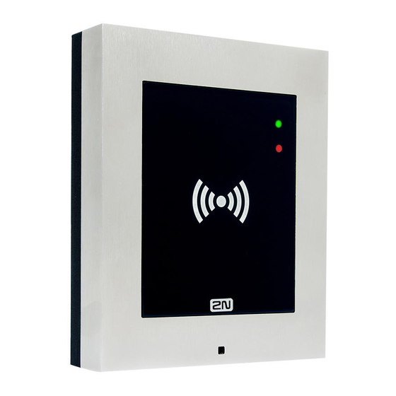
1. Popis produktu Here is what you can find in this section: 1.1 Components and Associated Products 1.2 Terms and Symbols Basic Properties ® Access Unit is an elegant and reliable access IP system equipped with a number of useful functions, which are not always common in devices of this category. ®... - Page 5 intercom either from a 12V power supply or directly from your PoE-supporting LAN. ® To configure 2N Access Unit , you need a PC equipped with any Internet browser. ® To manage extensive intercom installations easily, use the Access Commander Advantages of Use Elegant design Weather resistance...
-
Page 6: Komponenty A Související Produkty
1.1 Komponenty a související produkty Basic Units Part No. 916009 Part No. 916010 ® ® 2N Access Unit (13.56MHz + NFC) 2N Access Unit (125kHz) ® Supported auxiliary modules:2N Helios IP Verso modules are supported- RFID card reader (125kHz; 13.56MHz), keypad, 5-button module, Wiegand, etc. - Page 7 Frames Part No. 9155012 Part No. 9155011 Flush mounting frame, 1-module Flush mounting frame, 2-module Covering frame for the 1-module Covering frame for the 2-module brick/plasterboard flush mounting box. This brick/plasterboard flush 1-module frame is used for connection of an OUT mounting box.
- Page 8 Part No. 9155022 Part No. 9155021 Wall mounting Wall mounting frame, 1-module frame, 2-module Covering frame for wall (surface) mounting.This 1-module Covering frame for frame is used for connection of an OUT card reader or keypad, wall (surface) for example. mounting.
- Page 9 Part No. 9155040 Part No. 9155033 ® Helios IP Verso - ® Helios IP 13.56MHz RFID Card Reader, Verso– 13.56 MHz NFC Preparation RFID Card Reader The card reader module works The card reader ® with 2N Access Unit as an module works with OUT card reader.
- Page 10 Part No. 9155037 Part No. 9155031 Part No. 9155032 ® ® 2N Helios IP Verso 2N Helios IP Wiegand Module ® Verso– keypad 2N Helios IP Verso – The Wiegand module helps you The numeric keypad 125kHz RFID Card Reader interconnect your system with module helps enter a The card reader module...
- Page 11 Mounting Accessories Part No. 9155014 Part No. 9155015 Flush mounting box, 1-module Flush mounting box, 2-module Part No. 9155061 Part No. 9155062 Backplate, 1 module Backplate, 2 modules ® ® The mounting boxes for 2N Helios IP Verso are compatible with the 2N Access Unit , refer to the table below: Part No.
- Page 12 ® 2N Helios IP Verso– Covering frame for the 2-module brick/plasterboard flush Flush 9155012 mounting box. Remember to order the frame when you mounting order a 2-module flush mounting box, Part No. 9155015. frame, 2-module ® 2N Helios IP Verso– The box is designed for brick/plasterboard flush mounting of Flush 9155014...
- Page 13 ® The card reader module works with the 2N Access Unit an OUT card reader. The module supports cards, key fobs and/or other 13.56MHz standard carriers. ® Helios IP Verso ISO 14443AMifare Classic 1k & 4k, DESFire EV1, Mini, Plus 9155033 13.56MHz S&X, Ultralight, Ultralight C...
- Page 14 Electric Locks Part No. 932081E Part No. 932091E BEFO 11221 with momentary pin BEFO 11211MB with mechanical blocking Part No. 932071E 12V/230mA DC 12V/230mA DC BEFO 11211 low consumption A very short electric low consumption 12V/230mA DC pulse is enough to put You can set the lever the lock into the OPEN mechanically into the OPEN...
- Page 15 Part No. 932062E BEFO 321211 Part No. 932072E Part No. 932061E fail safe plus door signalling BEFO 31211 BEFO 11211MB with 12V/170mA momentary pin, mechanical fail safe blocking The fail safe lock is closed 12V/170mA DC when electricity is switched low consumption on.
- Page 16 Additional Modules Part No. 9159010 Security relay Part No. 9159013 Part No. 9159012 A simple, security enhancing add-on. Departure button Magnetic door contact Prevents lock Connects the logic A door installation set for door tampering. Installed input for door opening status identification. Used between the intercom, unlocking from inside for door protection, open door or...
- Page 17 Part No. 9137420E Part No. 9137421E External RFID card 13.56MHz and 125kHz USB RFID reader for connection card reader to PC using a USB External RFID card reader for interface. connection to PC using a USB Part No. 9134166E Suitable for system interface.
- Page 18 Part No. 9159030 Part No. 9159031 External 13.56MHz External 125kHz RFID Mifare RFID card card reader reader, Wiegand Secondary reader for Secondary reader for connection to an connection to an internal reader. Allows internal reader. Allows for control of card for control of card entry from both sides entry from both sides...
-
Page 19: Použité Zkratky, Termíny A Piktogramy
1.2 Použité zkratky, termíny a piktogramy The following symbols and pictograms are used in the manual: Safety Always abide by this information to prevent persons from injury. Warning Always abide by this information to prevent damage to the device. Caution Important information for system functionality. -
Page 20: Popis A Instalace
2. Popis a instalace Here is what you can find in this section: 2.1 Before You Start 2.2 Mechanical Installation 2.3 Electric Installation 2.4 Extending Module Connection 2.5 Mounting Completion ® TELEKOMUNIKACE a.s., www.2n.cz... -
Page 21: Než Začnete
2.1 Než začnete Product Completeness Check ® Check your Access Unit package for completeness before installation. ® Access Unit Brief manual ® TELEKOMUNIKACE a.s., www.2n.cz... -
Page 22: Mechanická Montáž
2.2 Mechanická montáž Mounting Types Overview Refer to the table below for a list of mounting types and necessary components. You can assemble multiple units in all the mounting types. Flush mounting - classic bricks incl. hollow bricks, thermally insulated walls, etc. What you need for mounting: a properly cut hole as instructed in the box package plaster, mounting glue, mounting foam or mortar as... - Page 23 Flush mounting - plasterboard What you need for mounting: a properly cut hole as instructed in the box package ® Access Unit flush mounting box and frame 1 module: box Part No. 9155014 , frame part No. 9155011 2 modules: box Part No. 9155015 , frame part No.
- Page 24 Caution The warranty does not apply to the product defects and failures arisen as a result of improper mounting (in contradiction herewith). The manufacturer is neither liable for damage caused by theft within an area that is accessible after the attached electric lock is switched on. The product is not designed as a burglar protection device except when used in combination with a standard lock, which has the security function.
- Page 25 Caution Make sure that the diameter of the dowel holes is accurate to avoid falling out of the dowels! Use the mounting glue to secure the dowels if necessary. Make sure that the depth of the dowel holes is accurate! Do not use low-quality dowels to avoid falling out of the dowels of the wall! Having removed the front panel, make sure that no dirt gets inside the...
- Page 26 Module Installation 2.2.1 One Module Box 2.2.2 Two Module Box ® TELEKOMUNIKACE a.s., www.2n.cz...
- Page 27 2.2.1 Krabice pro jeden modul Flush mounting - classic bricks ® TELEKOMUNIKACE a.s., www.2n.cz...
- Page 28 Flush mounting - plasterboard ® TELEKOMUNIKACE a.s., www.2n.cz...
- Page 29 ® TELEKOMUNIKACE a.s., www.2n.cz...
- Page 30 Module flush mounting ® TELEKOMUNIKACE a.s., www.2n.cz...
- Page 31 ® TELEKOMUNIKACE a.s., www.2n.cz...
- Page 32 Wall (surface) mounting ® TELEKOMUNIKACE a.s., www.2n.cz...
- Page 33 ® TELEKOMUNIKACE a.s., www.2n.cz...
- Page 34 ® TELEKOMUNIKACE a.s., www.2n.cz...
- Page 35 2.2.2 Krabice pro dva moduly Flush mounting - classic bricks ® TELEKOMUNIKACE a.s., www.2n.cz...
- Page 36 ® TELEKOMUNIKACE a.s., www.2n.cz...
- Page 37 Flush mounting - plasterboard ® TELEKOMUNIKACE a.s., www.2n.cz...
- Page 38 Module flush mounting ® TELEKOMUNIKACE a.s., www.2n.cz...
- Page 39 ® TELEKOMUNIKACE a.s., www.2n.cz...
- Page 40 ® TELEKOMUNIKACE a.s., www.2n.cz...
- Page 41 ® TELEKOMUNIKACE a.s., www.2n.cz...
- Page 42 Wall (surface) mounting ® TELEKOMUNIKACE a.s., www.2n.cz...
- Page 43 ® TELEKOMUNIKACE a.s., www.2n.cz...
- Page 44 ® TELEKOMUNIKACE a.s., www.2n.cz...
-
Page 45: Elektrická Instalace
2.3 Elektrická instalace ® This subsection describes how to install the modules and connect the2N Access Unit to the power supply and LAN and how to connect other elements. Version A - Stand-alone access unit ® Place the 2N Access Unit on the flush mounting box / pre-drilled holes with dowels and pull the cables through the bottom holes. - Page 46 PoE power supply ® Access Unit is compatible with the PoE 802.3af (Class 0 – 12.95 W) technology and can be fed directly from the LAN via the compatible network elements. If your LAN does not support this technology, insert a PoE injector, Part No. 91378100, between ®...
- Page 47 Legend to the figure PoE, LAN (PoE according to 802.1af) terminals RD, TD IN1, IN2 and IN3 terminals used as an input in the passive/active mode (−30 V to +30 V DC) for departure button, open door sensor, ESS etc. IN1, connection IN2,...
- Page 48 Factory Reset ® Access Unit is equipped with a RESET button , which is located between the LED indicators (LED1 and LED2 as shown in the figure below) in the right-hand upper part of the unit . Press the button shortly (< 1 s) to restart the system without changing configuration.
- Page 49 Wait untilthe red and green LEDs in the right-hand bottom part of the motherboard shine simultaneously (approx. 20 s). Wait until the red LED goes off (approx. 5 s). Release the RESET button. The following network parameters will be set after restart: IP address: 192.168.1.100 Network mask: 255.255.255.0 Default gateway: 192.168.1.1...
- Page 50 Available Switches Location Name Description Relay Passive switch:NO/NC contact, up to 30 V / 1 A AC/DC Basic Active switch output:8 up to 12 V DC depending on power unit Output supply (PoE: 10 V; adapter: power supply voltage minus 2 V), up to 400 mA Warning When you connect a device containing a coil, such as a relay or an...
-
Page 51: Připojení Rozšiřujících Modulů
2.4 Připojení rozšiřujících modulů ® Access Unit allows to connect following extending modules: Infopanel Klávesnice 125kHz RFID card reader 13.56MHz RFID card reader I/O modul Electronic buttons Wiegand modul Security relay Module Bus Interconnection ® All the modules that can be connected to Access Unit are interconnected via a bus. - Page 52 Basic unit Consumption [W] (571v3) (Maximum value) At relax OUT 1 Total Idle consumption Full load [ Special Module (Maximum elements (Minimum value) value) Basic unit (571v3) Infopanel(version 2) 0.17 0.64 Klávesnice(579v2) 0.20 1.55 125kHz RFID card reader (584v2) 13.56MHz RFID card reader 0.42 0.89 (583v2)
- Page 53 125kHz RFID Card Reader Module ® The 125kHz RFID card reader module ( Part No. 9155032 ) is one of the Access Unit elements and is used for reading RFID card Ids in the 125 kHz band. ® The module contains two bus connectors for2N Access Unit These two connectors are fully interchangeable and can be used either as inputs from the basic unit or outputs to other modules.
- Page 54 module name in the Module name parameter in the Hardware / Extenders menu. RELAY1 RELAY1 terminals with accessible 30 V / 1 A AC/DC NO/NC contact RELAY2 RELAY2 terminals with accessible 30 V / 1 A AC/DC NO/NC contact IN1 terminals for input in passive/ active mode (−30 V to +30 V DC) OFF = open or U >...
- Page 55 unconnected. The module package includes a 220 mm long interconnecting cable. Name tag dimensions: 69.2 (W) x 86.7 (H) mm (dimensional tolerance: +0; - 0.5 mm). For the printing template refer towww.2n.cz Wiegand Module ® The Wiegand module ( Part No. 9155037 ) is one of the Access Unit elements...
- Page 56 Isolated 2-wire WIEGAND IN Reader Isolated open LED OUT switched against GND (up to LEDOUT 24 V / 50 mA) +U (5 to 15 V DC) WIEGAND OUT power supply input +UIN OUT, OUT, Isolated 2-wire WIEGAND OUT GND2 Control Isolated input for open LED IN, input activated by Panel LEDIN...
- Page 57 Installation: The Security relayis installed onto a two-wire cable between the access unit and the electric lock inside the area to be secured (typically behind the door). The device is powered and controlled via this two-wire cable and so can be added to an existing installation.
- Page 58 Connection: ® TELEKOMUNIKACE a.s., www.2n.cz...
-
Page 59: Dokončení Montáže
2.5 Dokončení montáže Mounting Completion Check the connection of all wires and the RJ-45 plug to the pigtail (adapter) connected to the motherboard. Caution Make sure that the terminals of all the unused connectors are tightened properly to avoid sound vibrations. Frame Mounting Check the frame sealing before fitting the frame. - Page 60 ® TELEKOMUNIKACE a.s., www.2n.cz...
-
Page 61: Údržba
3. Údržba Cleaning If used frequently, the device surface, the keypad in particular, gets dirty. Use a piece of soft cloth moistened with clean water to clean the device. You are recommended to follow the principles below while cleaning: Do not use aggressive detergents (such as abrasives or strong disinfectants). Use suitable cleaning agents for glass lens cleaning (cleaners for glasses, optical devices, screens, etc.). -
Page 62: Technické Parametry
4. Technické parametry Audio Speaker:0.8 W / 8 Ω Interface Power supply:12 V ±15% / 2 A DC (3 A if there is a larger number of modules) and/or PoE PoE:PoE 802.3af (Class 0 - 12.95W) LAN::10/100BASE-TX with Auto-MDIX, RJ-45, connecting block or pigtail RJ-45 Recommended cabling:Cat-5e or higher Supported protocols:DHCP opt. - Page 63 Mechanical properties Cover:Robust zinc cast with surface finish Operating temperature:-40°C to 60°C Operating relative humidity:10%-95% (non-condensing) Storage temperature:-40°C to 70°C Dimensions: Wall (surface) mounting frame: 1 module: 107 (W) x 130 (H) x 28 (D) mm 2 modules: 107 (W) x 234 (H) x 28 (D) mm Flush mounting frame: 1 module: 130 (W) x 153 (H) x 5 (D) mm 2 modules: 130 (W) x 257 (H) x 5 (D) mm...
-
Page 64: Doplňkové Informace
5. Doplňkové informace Here is what you can find in this section: 5.1 Troubleshooting 5.2 Directives, Laws and Regulations 5.3 General Instructions and Cautions ® TELEKOMUNIKACE a.s., www.2n.cz... -
Page 65: Řešení Problémů
5.1 Řešení problémů For the most frequently asked questions refer to faq.2n.cz ® TELEKOMUNIKACE a.s., www.2n.cz... -
Page 66: Směrnice, Zákony A Nařízení
5.2 Směrnice, zákony a nařízení Europe ® Access Unit conforms to the following directives and regulations: Directive 1999/5/EC of the European Parliament and of the Council, of 9 March 1999 – on radio equipment and telecommunications terminal equipment and the mutual recognition of their conformity Directive 2006/95/EC of the European Parliament and of the Council of 12 December 2006 on the harmonisation of the laws of Member States relating to electrical... - Page 67 NOTE: This equipment has been tested and found to comply with the limits for a Class B digital device, pursuant to part 15 of the FCC Rules. These limits are designed to provide reasonable protection against harmful interference in a residential installation. This equipment generates, uses and can radiate radio frequency energy and, if not installed and used in accordance with the instructions, may cause harmful interference to radio communications.
-
Page 68: Obecné Pokyny A Upozornění
5.3 Obecné pokyny a upozornění Please read this User Manual carefully before using the product. Follow all instructions and recommendations included herein. Any use of the product that is in contradiction with the instructions provided herein may result in malfunction, damage or destruction of the product. The manufacturer shall not be liable and responsible for any damage incurred as a result of a use of the product other than that included herein, namely undue application and disobedience of the recommendations and warnings in contradiction herewith. - Page 69 Electric Waste and Used Battery Pack Handling Do not place used electric devices and battery packs into municipal waste containers. An undue disposal thereof might impair the environment! Deliver your expired electric appliances and battery packs removed from them to dedicated dumpsites or containers or give them back to the dealer or manufacturer for environmental-friendly disposal.
- Page 70 2N TELEKOMUNIKACE a.s. Modřanská 621, 143 01 Prague 4, Czech Republic Phone: +420 261 301 500, Fax: +420 261 301 599 E-mail: sales@2n.cz Web: www.2n.cz ® TELEKOMUNIKACE a.s., www.2n.cz...
Need help?
Do you have a question about the 2N Access Unit 916009 and is the answer not in the manual?
Questions and answers