
Summary of Contents for Giatec Scientific SURF
- Page 1 ™ Smart Concrete Testing Technologies User Manual Surf ™ USER MANUAL SURF ™ S U R F A C E R E S I S T I V I T Y C O N C R E T E U S I N G...
-
Page 3: Table Of Contents
™ TABLE OF CONTEN TS PACKAGE CONTENTS ....................III WARRANTY ........................V SAFETY INSTRUCTIONS .................... 1 ....................1 ENERAL UIDELINES INTRODUCTION TO GIATEC SURF™ ............... 4 ..............4 LECTRICAL RESISTIVITY OF CONCRETE ........................5 PPLICATIONS ....................6 EASUREMENT ONCEPT ......................8... - Page 4 User Manual Surf ™ TERMS AND CONDITIONS OF SALE ..............39 ("SALE AGREEMENT") A: END USER SOFTWARE LICENSE ..........46 XHIBIT © Giatec Scientific Inc.
-
Page 5: Package Contents
User Manual Surf ™ PACKAGE CONTEN TS Item Photo Surf Measurement ™ Device Surf Cell with ™ Connector Cable Verification Dongle (High Range +Low Range) Handheld probe (optional accessory) Surf Data Monitor ™ Software External Power Supply © Giatec Scientific Inc. - Page 6 User Manual Surf ™ USB Communication Cable Conductive Gel Conductive pads Note: Figures displayed above are not in scale. © Giatec Scientific Inc.
-
Page 7: Warranty
Product’s use. This Warranty is voided immediately if repair, modification (to include upgrades, expansions or usage or addition of non-manufacturer parts or accessories), alteration or other service is attempted other than by Giatec. In this regard, the integrity © Giatec Scientific Inc. - Page 8 Giatec in writing. THE WARRANTY SET FORTH IS EXCLUSIVE AND NO OTHER WARRANTY, WHETHER WRITTEN OR ORAL, IS EXPRESSED OR IMPLIED. GIATEC SCIENTIFIC INC. SPECIFICALLY DISCLAIMS THE IMPLIED WARRANTIES OF MERCHANTABILITY AND FITNESS FOR A PARTICULAR PURPOSE.
-
Page 9: Safety Instructions
SAFETY INSTRUCTIONS This chapter contains important safety instructions that you must follow when operating Surf™ and keeping it in storage. Read the following before any operation to ensure your safety and to keep the instrument in good condition. Keep the user manual in a safe place for future reference. - Page 10 OPERATION WARNING • Device AC Input Voltage: 5V, 250 mA • Only use the provided power supply adapter for operating Surf ™ • Do not perform measurement at circuits directly connected to Mains (Live circuit). •...
- Page 11 User Manual Surf ™ ATTENTION • Location: Indoor • Relative Humidity: 5% to 90% • Temperature: 0°C to 60°C © Giatec Scientific Inc.
-
Page 12: Introduction To Giatec Surf
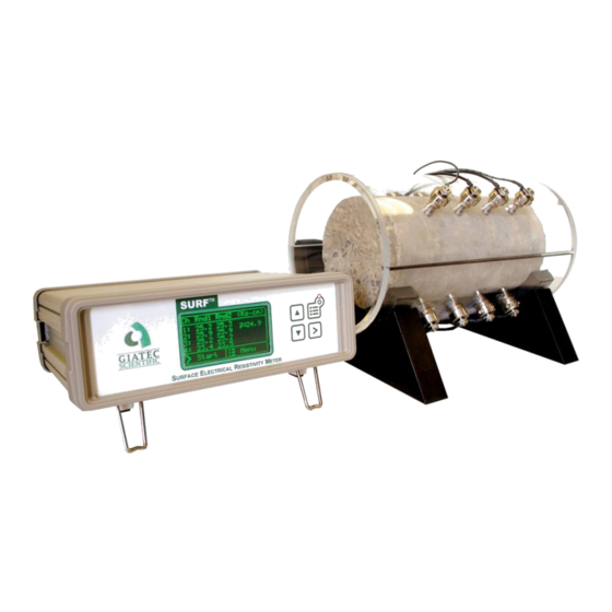
Surf ™ INTRODUCTION TO GIATEC Surf™ Giatec Surf™ is an advanced laboratory test device for measuring the surface electrical resistivity of hardened concrete cylinders or cores using the Four- Electrode measuring technique. Surface electrical resistivity technique has been standardized by AASHTO T 385. -
Page 13: Applications
28-Day Surface Chloride Charge Passed as per ASTM C1202 Resistivity Penetration (Coulombs) (kΩ.cm) High >4,000 <10 Moderate 2,000-4,000 10-15 1,000-2,000 15-25 Very Low 100-1,000 25-200 Negligible <100 >200 Adapted from Kessler et al. 2005 At 23 °C © Giatec Scientific Inc. -
Page 14: Measurement Concept
. Therefore, the electrical impedance can be also represented by a magnitude (Z) and a phase angle (φ) (Fig.1). Both the magnitude and phase angle of such a vector could vary depending on the frequency of the applied current. © Giatec Scientific Inc. - Page 15 (Resistance) Figure 1: Impedance vector: Real and Imaginary components Fig. 2 depicts the general concept behind the measurement of surface electrical resistivity using Giatec Surf ™ Figure 2: Schematic view of the test setup and the concept One widely accepted setup is the Wenner array where the four electrodes are situated in a straight line and equally spaced;...
-
Page 16: Device Overview
The back panel provides connection terminals to the sample holder of the device. ™ Figure 3: Surf Measuring Device The front panel of the measuring device includes display, as well as, the control keypad. The sample holder electrodes are connected to the measuring device using the cables included in the package. -
Page 17: Sample Holder
™ resistivity around the test sample as specified by AASHTO T 385 standard. It also reduces evaporation rate during the test. The sample holder has four sets of electrodes, placed at 90˚array. © Giatec Scientific Inc. - Page 18 User Manual Surf ™ Figure 6: The Surf™ sample holder 1. Sample holder supports 2. Sample holder lid 3. Electrode(s) 4. Connection cables Handheld Probe (optional) Handheld probe is design to test concrete samples which do not fit in the sample holder.
-
Page 19: Test Setup
User Manual Surf ™ T E S T S E T U P To start using Surf , the user must set up the concrete sample in the sample ™ holder. Surf sample holder provides a convenient approach to setting up ™... - Page 20 Step 2: Follow the instructions in Fig. 8 to connect the other end of the cable to any of the channels on the back of the surf device. Step 3: Wet the sponges and place them at the tip of the electrodes.
-
Page 21: Device Operation
Before turning on the device, make sure that the sample holder is appropriately connected to the device. TAND LONE PERATION The main power switch of Surf is located on the front panel of the device. ™ Press and hold the power key to turn on the device. The LED light on the power key, as well as, the device display will turn on, showing the test parameters. - Page 22 T358 standard test procedure, the default settings of the device are set to meet the specifications and requirements of the standard. The signal frequency is set to 13 Hz and the nominal voltage is limited to 25 V in © Giatec Scientific Inc.
- Page 23 Sample Holder menu by pressing Up and Down buttons (Fig 13). The sample size and the electrode spacing affect the geometry factor used in calculating the resistivity value. Figure 15: Sample Holder © Giatec Scientific Inc.
- Page 24 The user needs to apply the appropriate geometry factors for calculating the ‘resistivity’ of concrete. Figure 17: Sample Holder To start the test, press the Menu key on the front panel to go to the Test Parameters page. Then press the Start key. © Giatec Scientific Inc.
- Page 25 The user can adjust the contrast of the LCD screen through Screen Contrast option available in the Main Menu (Fig. 17). You can adjust the contrast of the LCD using the Up and Down keys. Figure 19: The Screen Contrast menu © Giatec Scientific Inc.
-
Page 26: Ata Onitor Oftware Peration
Surf ™ ONITOR OFTWARE PERATION Click on the Surf Data Monitor icon on the desktop to launch the software. ™ Alternatively, you can open the software from Programs in the Windows Start Menu. You should first install Data Monitor Software on your computer. Please refer to the Installing Data Monitor Software section of the user manual. - Page 27 Figure 21: Start a New Test Session In the new wizard form (Fig. 20), enter the project name, and project description such as; the source of cylinders, operator, and special notes. Figure 22: New Project Wizard © Giatec Scientific Inc.
- Page 28 The user can select the test sample (i.e., A, B, or C) and perform the test. The measurements will be performed in two rounds, and the data will be stored in the table. If you need to repeat the test, reselect the same sample name, and start the measurements again. © Giatec Scientific Inc.
- Page 29 Table 2. Summary of Control Keys Icon Name Default Enabled When Start Default When the test is Save successfully completed or after pressing Stop Stop After pressing Start Reset the test Reset parameters/Clears all recorded data © Giatec Scientific Inc.
- Page 30 C) and perform the test. The measurements will be performed in two rounds, and the data will be stored in the table. If you need to repeat the test, reselect the same sample name, and start the measurements again. Custom Mode © Giatec Scientific Inc.
- Page 31 The test can theoretically adapt any sample size, with different probe spacing; hence, electrical resistance (instead of resistivity) is recorded in this mode. The Custom mode benefits from real-time data plotting (chart) which makes data visualization more convenient. © Giatec Scientific Inc.
-
Page 32: Firmware Upgrade
Figure 27: Real-time visualization of data in Custom mode IRMWARE PGRADE If there is any update for the firmware of the Giatec Surf device, the ™ firmware upgrade files will be sent to the customers. These files will be used to upgrade the firmware of the device. - Page 33 User Manual Surf ™ Figure 28: Firmware Upgrade The user has to turn on the device in the Firmware upgrade mode. To do so, hold the Up key and press the power switch on the front panel. © Giatec Scientific Inc.
- Page 34 If the device is not in the correct mode, the user is asked to follow the instructions and try again. Click on the verify button to check the status of the device. If the device is appropriately set to Firmware Upgrade mode, the following screen will appear. © Giatec Scientific Inc.
- Page 35 ™ Figure 30: Select Hex and Eep Upgrade files Select the appropriate .Hex and .Eep files provided by Giatec Scientific Inc. Click on the Upgrade button to start the upgrade. Upon completion, the following screen will appear and the device will return to the test mode: Figure 31: Firmware Upgrade ©...
-
Page 36: Device Verification
Surf ™ EVICE ERIFICATION Two different dongles are provided with Surf that can be used to ensure ™ the appropriate functionality of the device. One dongle is designed to verify the accuracy of low range measurements (less than 100 kΩ.cm); while the other dongle is for the high range measurement (typically in the range of 100 kΩ.cm to 1,000 kΩ.cm). - Page 37 After the verification process is finished, the results are displayed for each channel at low and high ranges. Figure 34: Device verification results A Failure message (i.e., Fail) indicates that the device requires recalibration or service. Please contact technical support. © Giatec Scientific Inc.
- Page 38 Select the Device Verification from Tools menu, and follow the instruction to perform the verification process. The results of the verification will be displayed in front of the channel name (Fig. 33). Figure 35: Device verification results © Giatec Scientific Inc.
-
Page 39: Messages
After trying all these trouble shooting steps, if the problem persists, please contact Giatec Scientific Inc. technical support for assistance. © Giatec Scientific Inc. - Page 40 If these procedures did not resolve the issue, please contact the technical support of Giatec Scientific Inc. for assistance. If there is any error in any of the channels, the device will not show any average value.
-
Page 41: Installing Data Moni Tor Software
If your computer is running an older version of Windows (i.e., XP or 2000), or if your computer does not have internet access, you have to install the driver manually. The driver file is located on the Surf Data Monitor CD. In ™... - Page 42 Device Manager. In Windows, you can access Device Manager under System in the Control Panel. Figure 40: Device Manager window Right click on the USB Serial Port, and select Update Driver Software. Figure 41: Update Driver Software © Giatec Scientific Inc.
- Page 43 Figure 42: Select Browse my computer Select the Driver provided on the software CD and click on Next to install the driver. Figure 43: Select the driver file and browse for the file on the CD © Giatec Scientific Inc.
-
Page 44: Nstalling Ata Onitor Oftware
The Setup file is an autorun application. If the autorun did not start automatically, start the setup by clicking on the setup file in the installation Figure 44: Click on Setup to start installing the Surf Data Monitor The setup wizard will guide you through the rest of the installation process. -
Page 45: Maintenance
Do not use abrasives or solvents. ERVICE If Surf™ does not turn on; check the power supply cord to see if it is connected properly. If Surf™ still does not work properly; review this user manual to make sure you are operating it correctly. -
Page 46: Surf ™ Technical Specifications
Value Measurement Channels Measurement Display on LCD LCD Display Area 65×33 mm Dimensions of Device 200×160×70 mm Software Surf™ Data Monitor Reading Range and Accuracy Reading Range Frequency range Accuracy 0.1 – 100 KΩ.cm 13 – 100 Hz ± (0.1+1%) 100 –... - Page 47 TERMS AND CONDITIONS OF SALE ("SALE AGREEMENT") Please read this Sale Agreement before using the Giatec Scientific Inc. (“Giatec”) product (the “Product”). By finalizing Your purchase order, You, the purchaser of the Product, and, if applicable, any end user (“End User”) on whose behalf You are making this purchase for (You and the End User are hereafter collectively referred to as “Customer”;...
- Page 48 Warranty provided herein, unless full payment for the purchase of the Product is not received. Giatec will respond to Customer support problems by phone or by email inquiry. If a support problem cannot be © Giatec Scientific Inc.
- Page 49 Product for repair, and (iii) damaged Product will not be accepted. If during the Warranty Period (as described herein) but following the initial 30 day period the Product is not working properly, Customer must contact Giatec Technical Support to confirm the problem and obtain return © Giatec Scientific Inc.
- Page 50 (to include but not limited to an extended warranty or any support, service or repair agreement). If found to have breached this Sale Agreement, Giatec is not liable for any amount above the aggregate dollar amount paid by Customer for the © Giatec Scientific Inc.
- Page 51 Product (the “Software”) only in accordance with the terms of the Software License Agreement, attached hereto as Exhibit A, and the Customer shall agree with its terms prior to installing the Software. © Giatec Scientific Inc.
- Page 52 Sale Agreement by Customer or others does not constitute a waiver and shall not limit Giatec's rights with respect to such breach or any subsequent breaches. Giatec expressly reserves the right © Giatec Scientific Inc.
- Page 53 Any non-English language translation of this Sale Agreement is done for local requirements and in the event of a dispute between the English and any non- English versions, the English version of this Sale Agreement shall govern. © Giatec Scientific Inc.
- Page 54 You may not remove or alter any trademark, trade names, product names, logo or other proprietary notices, legends, symbols or labels in the Software. License Grant © Giatec Scientific Inc.
- Page 55 ATTORNEY FEES) ARISING OUT OF THE USE OF OR THE INABILITY TO USE THIS SOFTWARE, EVEN IF GIATEC OR ITS SUPPLIERS OR DISTRIBUTORS HAVE BEEN ADVISED OF THE POSSIBILITY OF SUCH DAMAGES. BECAUSE SOME JURISDICTIONS DO NOT ALLOW THE EXCLUSION OR LIMITATION OF LIABILITY © Giatec Scientific Inc.
- Page 56 Agreement. This Agreement is governed by the laws of the Province of Ontario and any disputes or claims arising hereunder shall be under the exclusive jurisdiction of the courts situated in the City of Ottawa, Province of Ontario. © Giatec Scientific Inc.
- Page 57 Notes...
- Page 58 Notes...
- Page 59 Notes...
- Page 61 IATEC CIENTIFIC INC 245 M 300, ENTEN LACE UITE , ON, K2H 9E8, CANADA TTAWA : +1 (613) 240-7451 HONE : +1 (613) 280-1544 SUPPORT GIATECSCIENTIFIC GIATEC Version 2.1 Printed in Canada...
Need help?
Do you have a question about the SURF and is the answer not in the manual?
Questions and answers