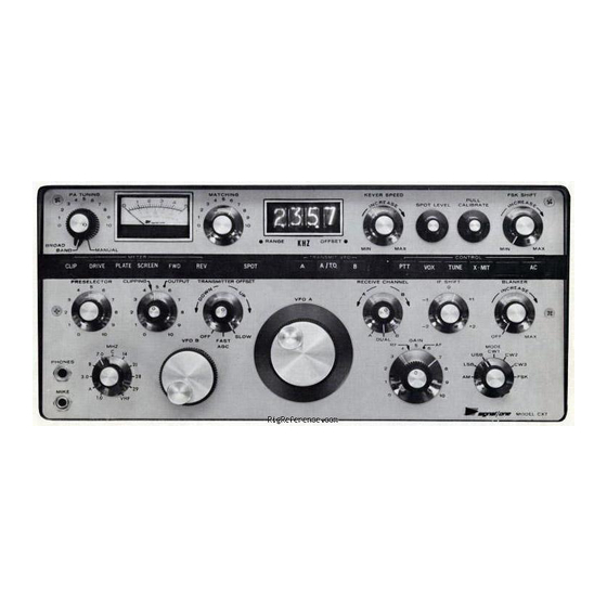
Advertisement
Important Installation, Adjustment & Operating Notes
It is extremely important that a few basic procedures and precautions be observed in order to derive from your new CX7 the
high level of performance designed into it, as well as to avoid damage to the power amplifier. Please read the following two
pages carefully, as well as the applicable portions of the instruction manual, before operating.
Using the CX7 with a separate linear amplifier
SSB:
The inherent transmit-receive switching speed of the CX7 is necessarily extremely fast in order to permit fill CW
break-in operation. Typical relays used in high powered amplifiers, however, require up to 10 milliseconds or more
to close. During the closing period, an open-circuit load is reflected back to the CX7, resulting in very high momentary
peak voltages which can damage the power amplifier or even the interconnecting coaxial cable fittings.
To avoid this problem in the CX7 during SSB (and AM) operation, a time delay of 10 milliseconds is introduced on
the build-up of RF output after switching to
tant that the CX7 not be operated in the
the amplifier's changeover relays complete closing within 10-12 ms. A monitor scope in the CX7
will indicate existence of an excessively slow P.A. relay as follows:
while feeding into the
continuously into the mike), operate either the
push-button. If the leading edge of the RF envelope appears smooth and slightly rounded, no problem
exists. If a short "spike" appears, the amplifier relay is excessively slow and you should contact SIGNAL/
ONE Customer Service for information on how to correct the problem.
CW:
The CX7 operates full break-in on CW, with envelope rise and fall times on the order of 2-3 milliseconds. Any ac-
companying power amplifier must complete its internal relay closure within this period (which is generally impossible
except for carefully selected vacuum-type relays), must be used with and electronic "T/R" switch, or must be manually
switched before operating the key (as with a foot switch, for example).
Adjustment of "CLIPPING" and "OUTPUT" Controls
CLIPPING: With the
OUTPUT
control until the meter just deflects off "0" on peaks while speaking in a normal voice. This set-up corresponds to
approximately 5-10 db of RF clipping, which is appropriate for most operation under medium to strong signal con-
ditions. To minimize backgrround noise, it is highly desireable to use a good cardiod mike (such as the EV 664 or
674 or SHURE 545) and to close-talk it. Under difficult conditions, transmitting effectiveness may be enhanced
by increasing the
ping than is required under any given circuit conditions will increase audio distortion, rather than intelligibility, at
the receiver. For any given microphone and operators's voice, the setting of the
tent and non-critical, so that the knob setting for various degrees of clipping may be once noted and then adjusted
as required thereafter, without need to monitor the meter
OUTPUT: With the
CLIPPING
advanced (with the
swing higher than "1" on the upper meter scale under any conditions, and no benefit can ever be derived (except
excessive background noise) by doing so. When
the CX7, the
OUTPUT
the linear in operation.
Rev. C.0
CX7 Adjustment & Alignment Notes
TRANSMIT
BROADBAND P.A.
MIKE
jack and audio tone sufficient to yield full transmitter output (or by whistling
control full CCW (minimum) and the
CLIPPING
control until the meter swings to half scale on occasional peaks. The use of more clip-
control set for 5-10 db normal clipping as described above, the
meter button depressed) until the meter just deflects off the "0" on peaks. It should not
DRIVE
control should be turned only to the point of slight meter deflection described above with
manually or by
or
PTT
mode with a separate amplifier until it is determined that
switch on the mike or the CX7 manual
PTT
CLIPPING
meter button depressed, adjust the
CLIPPING
indication.
is fed back from a separate power amplifier into
EXTERNAL ALC
TN9
operation. It is extremely impor-
VOX
RF OUTPUT
TRANSMIT
CLIPPING
control is quite consis-
OUTPUT
control should be
line
CLIPPING
TN9-1
Advertisement
Table of Contents

Summary of Contents for signal one CX7
- Page 1 Important Installation, Adjustment & Operating Notes It is extremely important that a few basic procedures and precautions be observed in order to derive from your new CX7 the high level of performance designed into it, as well as to avoid damage to the power amplifier. Please read the following two pages carefully, as well as the applicable portions of the instruction manual, before operating.
- Page 2 If meter reads S-9 or greater, (for REV PWR at or below S-3) operation will not damage the CX7. NEVER OPERATE THE CX7 IN THE BROAD- BROADBAND BAND P.A. POSITION IF THE RATIO OF FWD PWR READING TO REV PWR READING IS LESS THAN 3:1!


Need help?
Do you have a question about the CX7 and is the answer not in the manual?
Questions and answers