
Summary of Contents for OPTOTRONIX AURORA LCU EV2O
- Page 1 FINEST SCALE LIGHTING TECHNICS. FINEST SCALE LIGHTING TECHNICS. AURORA LCU I G H T O N T R O L N I T MANUAL Exclusive Dealer Download latest at Version: www.Optotronix.de ...
-
Page 2: Technical Data
Pay attention to notes and tipps marked with a before first operation of the lighting‐ system! With the AURORA LCU you purchased a high‐quality and modern lighting system. We hope you enjoy lighting up your aircraft and ask you to read the following instructions carefully. Technical Data Dimension 48x16mm Height ... -
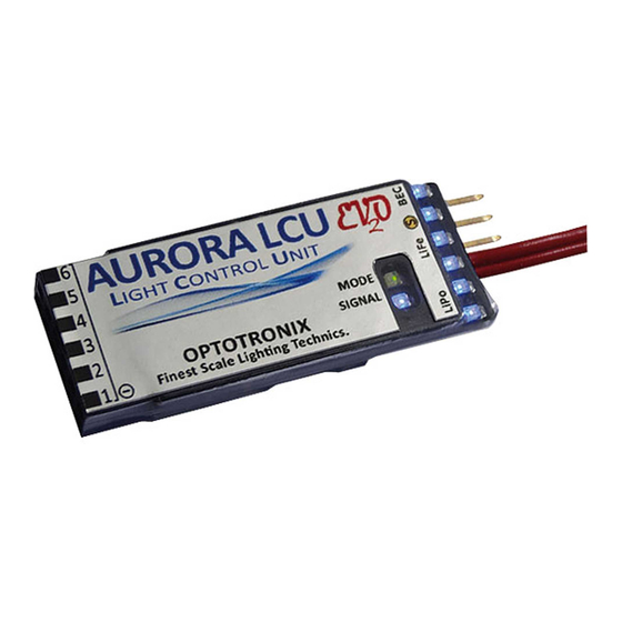
Page 3: Interface And Operation
Interface and Operation Status‐LEDs Of the 6 light outputs and display of battery state of charge Receiver Signaö Light Outputs (6x) Battery / Top: MINUS Bottom: PLUS Button „Set“ PLUS‐wires can be put together. MODE‐LED Shows if LCU is active and blinks if battery state of charge is < 30% SIGNAL‐LED Lights permanently if signal is active and valid. Blinks in Stand‐Alone Mode. If there is no valid signal, LCU goes into sleep mode after 5sec. After reactivation of receiver, also the LCU reactivates. Functional Principle The following figure shows how the AURORA LCU works. Light Function and Activation Point can be programmed for each light output. For controlling the light outputs by transceiver, use a triple switch or proportional slider on your transceiver. ... -
Page 4: Battery Recommendation
Connection of Supply and Receiver The AURORA LCU is powered by 1s/2s/3s Lipo Batteries, 2s/3s LiFePO Batteries, 3‐10s NiMh Batteries or with a BEC Voltage between 3,2V und 13,0V. The PLUS supply line ist red, the MINUS line is marked by a black line. The most efficient operation (Least power dissipation at resistors and lowest system weight) works with 1s cell Lipo. Attention: 1s LiFePO batteries are not recommended for powering Power LEDs (1Watt / 3Watt) because the little lower battery voltage means a lower brightness of LEDs. ... - Page 5 Connection of Receiver For operation of the AURORA LCU connect the patch cable (yellow – red – brown) to the signal input and to the receiver. To become familiar with the operation of the AURORA LCU , you can also connect to a servo tester. The signal input is electrically completely separated from the receiver, so negative reactions to the receiver are excluded. If there is no signal (no receiver is connected or invalid signal / defective signalwire) the blue Signal LED is NOT lighting up. If there is no valid signal for more than 5sec (receiver is deactivated), the AURORA LCU also deactivates and stays in Sleep Mode. As soon a valid signal is present again, the AURORA LCU wakes up. Receiver Supply Voltage 3,1V – 13,0V BEC 1s / 2s / 3s Lipo 2s / 3s LiFePo FailSafe Emergeny Lighting A very important and useful function is the indication of signal disruptions during the flight, live at the sky. If the mode is in FailSafe Mode because of weak signal or signal disruptions, the AURORA LCU starts a Emergeny‐Lighting‐Mode. All outputs – even permanent light outputs ‐ of the AURORA LCU are flashing very fast. This indication will be active as long as the FailSafe phase is active, but at least 2sec! ...
- Page 6 ‐ only at one pin. + ‐ If multiple LEDs are connected to one output in parallel, the PLUS wires can be combined to one. Because the AURORA LCU can provide high currents, the output connector is a female one, so that it is not possible to have a short circuit due to accidentally touching with metallic parts. LEDs are connected by using the connected pin rail. For more easy soldering, put the pin rail into the AURORA LCU during soldering process. A very easy and comfortable solution is the Light Plug 6 from Optotronix accessories. If you like to have a separate connector for each output, use the Light Connector Cables from Optotronix accessories. ...
- Page 7 Multiple LEDs can be connected in parallel. Consider Max.‐Current! Resistor in series ‐ consider LED Polarity! Multiple LEDs can be connected in parallel to one light output of the AURORA LCU . The output current of max 3A e.g. allows to connect 4 pieces of 3Watt‐Power Landing Lights in parallel to one output. ...
- Page 8 makes it possible to drive up to 6 small or 3 big afterburner rings simultaneously. The AURORA LCU offers 10 different and true to original afterburner effects. A very special feature by Optotronix is the afterburner random generator, which generates a very realistic flame effect. In contrast to low cost lighting electronics, there is no loop of the same flame effect all the time. Instead, no second of the flame effect looks like another. Attention: The AURORA LCU only can be used in scale‐lighting‐mode (positions lights, flashes, beacon) OR in afterburner‐mode, because you control the afterburner effect by ...
- Page 9 Connection of Multi‐Gun LEDs The AURORA LCU now offers also the simulation of machine gun effects by using LEDs, this feature is used espacilly for lighting up weapon dummies of military models. The Multi‐ Gun Light Effect is fully random generated and looks very realistic: the fire sequences are irregular and the frequency is taken from the originals. Use bright, orange or Yellow LEDs to install into weapon dummies. Connect it to output 6, which ...
- Page 10 Resistor Table The required resistor for your desired LED Type can be gathered from the following table. The values can be used both for operation directly at a battery and for operation at the AURORA LCU . Also pay attention to the required power‐rating of the resistor. For choosing the supply, generally consider: The voltage should be as small as possible, because LEDs do not need more than 3,5V (red/ yellow only 2,4V). Everything above that voltage has to be converted into heat in the series‐resistor. That is why the operation at 3,6V/4,8V (3s/4s NiMh) or 3,7V 1s Lipo) has to be preferred. ...
-
Page 11: Battery Test
Battery Test The battery test function of the AURORA LCU can be started at any time by short pressing the “Set” button, during the battery test (about 3 seconds) the connected LEDs are disabled! At first, 2 of the blue status‐LEDs are blinking up, showing which battery type is programmed (Lipo, LiFe, or BEC). The voltage level of the battery can be read with the 6 blue status‐LEDs of the AURORA LCU . If 4 LEDs are active, the battery state of charge is 60‐75%. If no LED is active any more, the battery should be disconnected and recharged. ... - Page 12 Programming Battery Type At first you have to program the used battery supply (Lipo, LiFePO, BEC / others). Before programming, connect the fully charged battery to the AURORA LCU . By pressing the Button short (“zapping”) you can choose between the offered three types (Lipo, LiFePO, BEC / others). The battery type is displayed by two blue status‐LEDs (see graphic below). Save the choosed battery type by pressing the Button for two seconds. The number of used cells will be detected automatically and it will be shown by blinking of the blue status‐LEDs. If you choose “others” (e.g. for BEC‐supply), the safety‐shutdown will be deactivated, it will be displayed the supply voltage in six steps from 3,2V to 13V. ...
- Page 13 The following table shows the functions provided by the AURORA LCU : Factory Nr. Light Function …delayed …long delayed setting 0 A4, A5, A6 Permanent Light Water Airplanes & Gelicopter Landing Light Sequence: 1 Alternating lighting up oft wo landing lights, only available on A5 & A6! 2 Single Flash 3 Single Flash 4 A3 Single Flash 5 Blink (150ms on) 6 ...
- Page 14 Multi‐Gun Effects 41 Gattling Gun (only on A6) 42 MG Feuer (only on A6) 43 MK Feuer (only on A6) After the program mode is completed, the AURORA LCU restarts. COMPLETE ‐ The AURORA LCU is fully programmed an can be used. WICHTIG Connect Landing Lights beginning with Output 6 and Flashlights beginning with output 1. So the AURORA LCU ...
-
Page 15: Reset To Factory Settings
Reset to Factory Settings The AURORA LCU can be easily reset to factory settings. Turn on the AURORA LCU . Keep the button pressed till the welcoming flash light sequence is ended. Since this lasts 2 seconds you have enough time after connecting the battery to press the button and hold. The start of the programming mode is indicated by a 3 second long, very fast flashing of all LEDs. Keep the button permanently pressed also during this sequence until the AURORA LCU ... -
Page 16: Warranty And Legal Information
Optotronix issues a 24-month warranty for the AURORA LCU . There is no right to repair, Optotronix reserves the right to share in case of warranty the device against an equivalent product if a repair is not possible. This warranty expires when the module takes damage resulting from misuse, because the...
Need help?
Do you have a question about the AURORA LCU EV2O and is the answer not in the manual?
Questions and answers