Table of Contents
Advertisement
Quick Links
Advertisement
Table of Contents

Summary of Contents for Stienen BE PL-9000
- Page 1 PL-9000(-i) USER MANUAL FOR THE PL-9000(-i) POULTRY COMPUTER V 01.48.0...
- Page 2 Shut down power before opening the poultry computer! This poultry computer contains exposed live parts! Only to be opened by authorized personnel! WARNING Although utmost care has been given to the quality of this equipment during the design and manufacturing stages, technical malfunctions can never be ruled out.
-
Page 3: Table Of Contents
Contents Page INTRODUCTION........................1 Ventilation groups......................1 Heating controls ........................2 Cooling ..........................2 Humidification ........................2 Timers ..........................2 Counters ..........................2 Window..........................3 Keyboard..........................3 OVERVIEW .......................... 6 MAIN MENU ......................... 7 CLIMATE CONTROLS ......................7 House temperature ......................7 Relative or absolute temperature setting ................8 Ventilation groups......................8 Heatings......................... - Page 4 CLEANING HR SENSOR, CO SENSOR OR MEASURING FAN WITH A HIGH-PRESSURE SPAY GUN IS NOT ALLOWED Remove the HR sensor and CO sensor from the room and store it somewhere safe before cleaning the room. Also screw the protection cap onto the plug of the extension cable to prevent water from penetrating into the plug.
-
Page 5: Introduction
The air distribution in the house is strongly influenced by the type of air supply system. Effective ventilation controls, as are integrated in the PL-9000 poultry computer, can achieve a good air quality at animal level with a low ventilation flow rate. It speaks for itself that good climate control contributes to the animals' well-being. -
Page 6: Heating Controls
You can use I/O modules to extend the number of outputs of the PL-9000 poultry computer, via the ST bus (module bus). The control computer indicates which output must be driven by the PL-9000 poultry computer. The poultry computer has a memory chip where all settings are saved into, to ensure that the settings are retained even when the voltage is lost. -
Page 7: Window
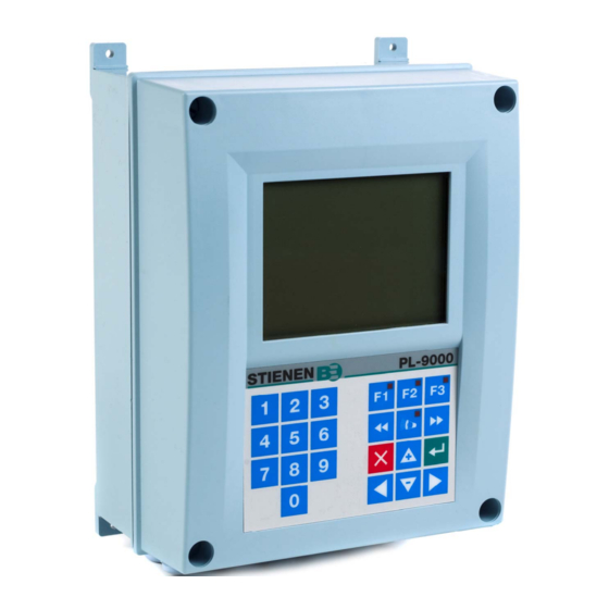
WINDOW Column with settings and/or measurements Column with calculated and/or Title bar corrected settings Screen number Graphic (function key F3) The calculated setting may differ from the value set by the user, due to the growth curve and/or compensations. You can use the key to Time &... - Page 8 Numerical keys (0..9) The numerical keys can be used to enter a screen abc2äàâçæå number, a value or text. You can select menu choice 10 by pressing key 0. def3éèêë .,1'-:+ jkl5 Entering text Numerical keys 2..9 can be used to change the name of mno6ñôöœø...
- Page 9 Alarm key Hot key for alarm screen. The LED in the alarm key lights if there is an alarm on one of the controls. Here you can switch the main alarm on and off. When the main alarm is off, the LED in the alarm key will flash to indicate that the main alarm is off.
-
Page 10: Overview
OVERVIEW Column number Column Symbol Description number Column with house numbers (user number) House not in use Status main alarm (alarm relay de-energized) Main alarm is switch off Alarm Alarm in house (alarm delay time is not yet elapse) Alarm in house (alarm delay time is elapse) Main alarm is switch off Heat request in house Heating... -
Page 11: Main Menu
MAIN MENU If you use access codes, it is advisable to write the code down and store it somewhere safe. If you forget the access code, you can no longer change any settings. As soon as one access code is active, you can only change the setting by entering the correct access code. -
Page 12: Relative Or Absolute Temperature Setting
RELATIVE OR ABSOLUTE TEMPERATURE SETTING Control Relative setting Absolute setting Main ventilation group Always relative to temperature in n.a. the house Ventilation groups Always relative to temperature in n.a. the house Heating 1..2 If the setting is between -9.9°C and If a value equal to or higher than +9.9°C, the setting is relative to the 10.0ºC is set, this will be an absolute... - Page 13 Current temperature This line displays the current average house temperature. Current ventilation If house ventilation is controlled using a measuring fan, the measured and calculated ventilation values will be shown in this line. If the fans do not have measuring fans or if a measuring fan is defective, the calculated ventilation will be equal to the “measured”...
- Page 14 Maximum flap opening = 100% The AQC flap without a measuring fan controls on the basis of the calculated main ventilation (main Current flap opening fan output). Minimum flap opening Main ventilation [%] Minimum Current Maximum at ventilation ventilation at ventilation Interval ventilation If interval ventilation has been activated by your installer, the display will show the menu item “Interval ventilation”.
- Page 15 Minimum and maximum ventilation The minimum and maximum flap opening can be set here. Current temperature This line shows the current average temperature on the basis of which the ventilation group is controlling. Calculated flap opening Control on the basis of temperature: The flap opening requirement is calculated on the basis of the temperature measured, the bandwidth, the minimum and maximum flap opening.
- Page 16 Cascade control Group [%] Max. 80% Hyst. Min. 5% [°C] Bandwidth control current Air inlet flap 1 87,5% D2 = air inlet flap 2 is closing O2 = air inlet flap 2 is opening 12,5% Min. Max. Group [%] Air inlet flap 2 Max.
-
Page 17: Heatings
HEATINGS Controlled heating Bandwidth Maximum heating Relative setting Current heating Minimum House temperature [°C] Temperature Current setting temperature House temperature setting Heating You can switch the heating on or off. Temperature setting The temperature on the basis of which the heating controls is relative to the house temperature, see page 7, if a temperature of below 10.0°C is set. -
Page 18: Cooling
On/off heating If the heating consists of on/off (non-modulating) heating, you can call up the operating hours of the heating. In addition to today's operating hours, the operating hours of the past 7 days and the total number of operating hours are shown as well. -
Page 19: Compensations Climate Control
the air speed and the temperature difference in the house would increase enormously. As this may easily cause a draught which would affect the animals the pressure control is switched off as soon as the hatches are open. The inlet flaps, which were being controlled on the basis of pressure, are now temperature-controlled. Humidification This window enables you to switch the humidification control on or off and to set the relative humidity percentage. - Page 20 Night setting You can use the night settings to create natural temperature behaviour between day and night by reducing the temperature setting by a couple of degrees during the night. In addition to the period when the night setting has to be active, you can also set the number of degrees by which the house temperature has to be increased/decreased during this period.
- Page 21 Bandwidth compensation If the outside temperature is part of the installation, the bandwidth of the main ventilation and/or air inlet flaps can automatically be adjusted to changes in outside temperature. As a result, it is possible to obtain a larger bandwidth at low outside temperatures and a smaller bandwidth at high outside temperatures.
- Page 22 Pressure control The underpressure can automatically be adjusted to the current outside temperature to create a higher underpressure when the outside temperature is low and a lower underpressure when the outside temperature is high. Example Pressure setting: 20 Pascal Compensation pressure: -0.3Pa/°C Starts outside temperature: 20°C...
- Page 23 RH / CO In addition to the ventilation control which controls on the basis of temperature, the further functionality of the poultry computer includes the possibility of controlling the ventilation/flap position on the basis of relative humidity or CO . This means that the ventilation effort will be increased if the result measured is higher than the “compensation start”...
- Page 24 Meteo The wind influence is adjustable between 0 and 9 For every ventilation group, your installer can set the (0 = no influence, 9 = maximum influence). wind direction by which the ventilation group must be corrected. Have your installer set “none” if you do not require wind correction.
-
Page 25: Growth Curves
GROWTH CURVES Several growth curves are available for gradual automatic adjustment of the climate in the house. A growth curve can consist of a maximum of 7 breakpoints. The current setting is determined on the basis of the growth curve, depending on the current day number. -
Page 26: Temperature Overview
TEMPERATURE OVERVIEW An overview of the temperature control or growth curve selected is shown. Animal weights equal to or greater than 10,000 grams are displayed in kilograms. I.e. 10,000 (grams) is shown as 10.0 (kg). Use the key to select the next/previous control, overview or sensor. - Page 27 Example: < > ) > OUTSIDE HOUSE. OUTSIDE HOUSE. OUTSIDE ALARM Absolute temperature limit setting: 35.0ºC 35.0ºC 35.0ºC Temperature setting: 22.0ºC 22.0ºC 22.0ºC Maximum alarm limit setting. 5.0ºC 5.0ºC 5.0ºC Current outside temperature: 18.0ºC 25.0ºC 31.0ºC Calculated maximum alarm limit 22.0+5.0 = 27.0ºC 25.0+5.0=30.0ºC 35.0ºC...
-
Page 28: House Status
Miscellaneous The alarm limits can be set separately for every individual control. You can put the house 'in use' or 'out of use', using the house status. You can also call up the status of the house by HOUSE STATUS pressing the F2 function key. -
Page 29: Silos
SILOS SILO CONTENTS Silo contents: The current silo contents are (stock or shortage) is indicated. You can also enter the filled volume per silo; this is then added directly to the silo contents and the filled counter is reset to 0 automatically. Attention! You can only enter a positive silo content when you press the enter key, any negative values are erased. -
Page 30: Counters
An overview of the counter readings is shown. In COUNTERS addition, you can set a dosing alarm in combination with the water and/or feed counters. If several water, feed and/or other counters have been installed, the counter readings of all identical counters (water, feed and/or other) are added together and shown in the corresponding column. -
Page 31: Clear All Counters
Clear counter CLEAR ALL COUNTERS The counter readings of the selected counter can be All counter readings are erased, contrary to the deleted in this screen. setting “Clear counter” for the individual counters, where only the counter readings of the selected counter are erased. -
Page 32: Timers
A maximum of 24 periods can be set on a timer. All times have to be consecutive times. The TIMERS difference between two times must be at least 1 minute. DOSAGE TIMERS The timer output of a dosing timer is linked to a counter input to enable the water and/or feed intake to be monitored. -
Page 33: Light Timers
LIGHT TIMERS When using a light timer it is also possible to use a lighting control so that the lighting is gradually switched on/off. A lighting control enables you to create ideal day and night conditions. Dim time 1 Dim time 2 100% Begin time 1 Begin time 2... -
Page 34: Week Programme
WEEK PROGRAMME 2 days You can use the “Week programme” to set the dosage timer so that it is not activated every day, but e.g. that it must be active 6 days and inactive 1 day (e.g. because 1 day a week should be without feeding). The details of timers 2 and 3 can be changed and/or called up in a similar manner. -
Page 35: Dosage Curves
DOSAGE CURVES If no growth curves have been installed for the climate control, you can set the day number of the dosing curve here (the dosing curves are off when the day setting is 000 and the day number will not be incremented automatically for a new day then). -
Page 36: Info
INFO The “Temperature”, “Counters” and “Timers” and “Silos” screens are identical to menu option “Overviews”. You can use the “Reset min/max temp.” setting to clear the min/max measurements in all temperature listings and to fill “Today” with the current value. ANIMAL DATA To mutate Lost... - Page 37 Overview mutations An overview of the mortality, the number of animals unloaded (out) and the number of animals added (in) per day is shown. Overview present animals An overview of the daily remaining number of animals in the house is shown. Entry date data This data in this screen has to be entered at the start of new entry (a new round).
-
Page 38: Alarm
ALARM Here you can switch the main alarm on and off. When the main alarm is off, the LED in the alarm key will flash to indicate that the main alarm is off. No alarm is generated anymore. Test (alarm test) Test “yes”: This enables you to test the operation of the alarm relay (siren). - Page 39 Module reset alarm Module continues to reset due to a fault, check the module No communication address Missing device address. Software version PL-9000 is too old, update software. No information from houses House not in use. No input assigned No input terminal number entered...
-
Page 40: System
This screen shows the device type as well as the software SYSTEM program version. Language: You can set the language of the screen texts here. The language in this example is set to ENG (English). You can also change the language by pressing and holding functional key F1 while simultaneously pressing the cursor key pointing to the right. -
Page 41: Maintenance And Check Up
MAINTENANCE AND CHECK UP Regular maintenance and checking of the equipment are essential for its proper operation. Don’t forget to clean the ventilation system when cleaning the houses. To minimize the energy consumption, it is important that the fans are clean. This also applies to the flaps, measuring fan and the ventilation tube.
Need help?
Do you have a question about the PL-9000 and is the answer not in the manual?
Questions and answers