Table of Contents
Advertisement
Quick Links
Advertisement
Table of Contents

Related Manuals for aquilar AquiTron AT-G-ALERT-C

Summary of Contents for aquilar AquiTron AT-G-ALERT-C
- Page 1 1100-2184 Rev 0...
-
Page 2: Table Of Contents
Table of Contents Introduction 1.1 About this Manual 1.2 Iconography 1.3 General Safety Statements Product Description 2.1 AT-G-ALERT-C Core Functions 2.1.1 Home 2.1.2 Navigation Buttons 2.1.3 Status Icons 2.1.4 Floor List 2.1.5 Room/Device list (each floor) 2.1.6 Settings 2.2 System Components 2.2.1 AT-G-ALERT-C Refrigerant Leak Monitor 2.2.1... - Page 3 3.12 Method 2: Set Modbus ID Manually Operation 4.1 Overview of Normal Operation 4.2 Alarm Detection 4.3 Fault Detection 4.4 Communication (Comm.) Error 4.5 Event History 4.6 Service Mode Screen Additional Information 5.1 Disposing of the Instrument 5.2 Service Center Locations 1100-2184 Rev 0...
-
Page 4: Introduction
1 Introduction 1.1 About this Manual Thank you for investing in an AquiTron AT-G-ALERT-C Refrigerant Leak Monitor. To ensure operator safety and the proper use of the system, please read the contents of this manual for important information on the operation and maintenance of the instrument. -
Page 5: General Safety Statements
CAUTION: DO NOT continue to use this equipment if there are any symptoms of malfunction or failure. In the case of such occurrence, de-energize the power supply and contact Aquilar Ltd. IMPORTANT: Before using this product, carefully read and strictly follow the instructions in the manual. -
Page 6: Product Description
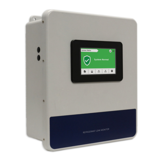
2 Product Description The AT-G-ALERT-C Refrigerant Leak Monitor provides centralised monitoring and alarming for multi-occupant applications utilising the AT-G-ALERT Refrigerant Leak Detectors. The AT-G-ALERT-C continuously monitors all connected devices for alarm and fault conditions and will provide alerts via the integrated colour touchscreen, audible buzzer, and built-in relays. -
Page 7: Navigation Buttons
2.1.2 Navigation Buttons Most screens have the following navigation buttons: Icon Icon Name Home Alarm list Fault list Comm error Floor list 2.1.3 Status Icons Each floor and room will use the following status icons: Icon Icon Name Alarm Fault Comm error Normal Not yet commissioned... -
Page 8: Room/Device List (Each Floor)
Figure 2 - Floor List 2.1.5 Room/Device list (each floor) Detailed view for each AT-G-ALERT / room in the system grouped on a given floor. Figure 3 - Room/Device List 1100-2184 Rev 0... -
Page 9: Settings
2.1.6 Settings Use the settings screen for system configuration changes. To access the Settings screen, tap the gear icon. Figure 4 - System Settings This screen is passcode protected to avoid unintentional changes. If not already logged in, the Passcode prompt will appear. Figure 5 - Passcode Enter the passcode for the AT-G-ALERT-C controller to unlock and allow changes. -
Page 10: System Components
2.2 System Components 2.2.1 AT-G-ALERT-C Refrigerant Leak Monitor The AT-G-ALERT-C Refrigerant Leak Monitor (AT-G-ALERT-C) provides centralized alarming and monitoring for all connected AT-G-ALERT Leak Detectors. 2.2.2 AT-G-ALERT Refrigerant Leak Detector The AT-G-ALERT Refrigerant Leak Detector provides refrigerant leak detection for occupied rooms in applications. 2.2.3 Ethernet Network Switch An Ethernet network switch is used to provide connectivity between the AT-G-ALERT-C Controller and individual gateways. - Page 11 The AT-G-ALERT-C provides centralised alarming and monitoring for all connected AT-G- ALERT devices. Figure 6 - AT-G-ALERT-C Overview Component Description PLC / Touch Screen USB Port Ethernet Port Fault Relay Alarm Relay Modbus Terminal Block Power (24V DC IN) Cable Entries (x4) 1100-2184 Rev 0...
-
Page 12: Installation
3.1 Network Overview IMPORTANT: Prior to installation, download the AT-G-ALERT-C floorplan spreadsheet available from Aquilar.co.uk or on the USB stick supplied with the controller. This spreadsheet has editable fields for Floor / Room and non- editable fields for Modbus ID and Gateway IP address. The floor and room fields are to be completed prior to installation in order to ensure correct wiring and function. - Page 13 Network Creating Notes: • To mark devices to be on the same floor, those devices must have the same floor name (capitalisation matters). The AT-G-ALERT-C will display a new “floor” tile for each unique name appearing in the floorplan spreadsheet, up to 16 distinct values.
-
Page 14: Floorplan Spreadsheet (Csv)
3.2 Floorplan Spreadsheet (CSV) When editing the AT-G-ALERT-C floorplan spreadsheet (data.csv) on a PC, it contains placeholder entries for all possible devices in the network. Insert the USB stick into a computer that has Excel software installed. 1. Open the flash drive and click the example CSV file titled “data.csv.” Figure 10 - Open the data.csv File In this file, there are columns labeled: Index, Floor, Room, Gateway, ModbusID, and IpAddress. -
Page 15: Gateway Ip Address
3. Save the floorplan spreadsheet as a .csv format and upload it onto the USB stick at the device root folder. The filename must be named as “data.csv” or the AT-G-ALERT- C will not be able to find the file when importing. 4. - Page 16 AT-G-ALERT device count IP for Gateway Order 192.168.0.1 192.168.0.2 192.168.0.3 192.168.0.4 192.168.0.5 192.168.0.6 192.168.0.7 The IP address for each Gateway may need to be changed by the user, since gateways ship with default IP 192.168.0.1. This can be done using a windows PC and the free Moxa utility.
- Page 17 Figure 13 – Broadcast Search 5. When discovered, the Gateway should show up in the table. Select its row and press Configuration. a. Note: if this step requires a password it is “moxa” Figure 14 – Gateway Configuration Navigate to the Network tab (the second tab). Figure 15 - Network tab 7.
- Page 18 8. If this gateway is the first in the network, its IP address is already correct – 192.168.0.1. If it is the second, change the last digit to be 192.168.0.2, etc. Figure 16 - Network Setting OK screen 9. Repeat this process for the remaining gateways in the system. The gateways contain powerful built-in troubleshooting features.
-
Page 19: Hardware Installation
3.4 Hardware Installation Mount the AT-G-ALERT-C in an accessible location for viewing alerts and responding to alarm conditions. Environment: place the AT-G-ALERT-C in an indoor setting free from the risk of exposure to water, high humidity or any hazardous conditions. Accessibility: ensure that the AT-G-ALERT-C’s touch screen is readily accessible for viewing alerts and responding to alarm conditions. -
Page 20: Battery For Persistent Memory
Note: Take care to ensure proper wiring for intended function: normally open and / or normally closed. Figure 18 - Wiring Relays 3.6 Battery for Persistent Memory When 24V DC power is lost to the AT-G-ALERT-C, a backup battery is used to save the current state of the system, including the event history and the date and time settings. - Page 21 Connect the Modbus cable to the gateway output as depicted below. Each gateway can support a maximum of 15 AT-G-ALERT devices connected in a Figure 19 - Wiring Gateways daisy chain fashion using the Modbus network cable. Leave no more than 30 cm for the wire tie-off to each AT-G-ALERT. The shield cable may be left floating or tied to electrical GND at the controller only.
-
Page 22: Connecting At-G-Alert
Modbus ID (number 2 through 16), and the unique IP address of the gateway to which they are connected. Additional resources for the AT-G-ALERT are available online. To download these resources, visit aquilar.co.uk or use the direct link: Here. Wiring Notes: •... -
Page 23: Upload Floorplan Spreadsheet
3.9 Upload Floorplan Spreadsheet 1. Power up the AT-G-ALERT-C. When the System Startup (Home) screen appears, access System Settings (gear icon). Figure 21 - System Status screen 2. After the System Setting screen appears, insert the USB stick containing the floorplan spreadsheet into the USB slot of the controller. -
Page 24: Method 1: Modbus Id Auto-Assign
1. Modbus ID Auto-assign: Automatically connect and set IDs using the integrated Magnetic Switch to pair each AT-G-ALERT to its install location. 2. Set Modbus ID Manually: Use the RS485 port on the controller to manually set the Modbus IDs, and then install according to the floorplan, while keeping track of assigned Modbus IDs. - Page 25 4. Tap the tile with the first room that is to be commissioned. Figure 24 – Tap the tile of room to commission This should open the Device Modbus Pairing Screen. 5. At the physical AT-G-ALERT device, have a co-worker tap the Magnetic Switch A (marked with a single dot “•”) with the magnetic wand for less than a second, and then pull the magnetic wand away.
- Page 26 6. Back at the AT-G-ALERT-C touchscreen, after the device has been put into the “Commissioning Mode”, tap Commission Device. When the device has successfully commissioned, a “Success” message will appear. If the commission was unsuccessful, an “Unable to Contact Device” message should appear and the network wiring should be checked.
- Page 27 8. On the Devices Screen there should be a green checkmark on the device that was just commissioned signaling that the commission was successful. Figure 28 - Green checkmark appears 9. Repeat these steps for each room on a floor and each floor in the building until all AT- G-ALERT devices have been commissioned.
-
Page 28: Method 2: Set Modbus Id Manually
3.12 Method 2: Set Modbus ID Manually Modbus IDs can be manually assigned to the AT-G-ALERT devices prior to wiring. Wire a single AT-G-ALERT Modbus port to the controller’s Modbus terminal block. It is recommended to use the EZ-wire kit available with the AT-G-ALERT-C controller for ease. 1. - Page 29 c. Hold the magnet wand to Magnetic Switch A (marked with a single dot “•” on the AT-G-ALERT) for 60 seconds. The device should beep at the end of 60 seconds to indicate reset. d. Remove the magnet wand and cycle power. The AT-G-ALERT will have reverted to default settings including default Modbus ID 1.
-
Page 30: Operation
4 Operation 4.1 Overview of Normal Operation The AT-G-ALERT-C provides centralised monitoring of all segments in the network with a 15-second scan rate. 4.2 Alarm Detection The AT-G-ALERT-C controller will provide instantaneous details for any AT-G-ALERT in the network experiencing an alarm condition. To respond to an alarm event: 1. -
Page 31: Fault Detection
4.3 Fault Detection The AT-G-ALERT-C controller will provide instantaneous details for any AT-G-ALERT in the network experiencing a hardware fault condition. To respond to a Fault event: Tap Mute to silence the alert. This will mute the buzzer at the controller for 30- minutes. - Page 32 To respond to a Comm. Error event: 1. Tap Details to open the Comm. Error screen to view the device(s) impacted. Figure 36 – System Status screen The Comm. Error screen will list the Floor/Room location, status, and network details for each affected AT-G-ALERT. Figure 37 - Comm.
-
Page 33: Event History
4.5 Event History The AT-G-ALERT-C will save new Alarm or Fault events to the Event History. This can be accessed from the Setting screen. The event history is a rolling list of 100 entries. In addition, entries tagged as neither alarm nor fault are created when a device status clears to normal. - Page 34 2. Tap UniApps from the pop-up menu that appears. Figure 40 - Tap UniApps 3. Select the System tab, and then Time & Date. Choose the date from the calendar tool on the left side of the screen and the time from the right side of the screen. Figure 41 - Choosing the time and date 4.
-
Page 35: Service Mode Screen
4.6 Service Mode Screen This utility will disable the audible buzzer and set the relays to their default (normal) position for 30 minutes in order to facilitate maintenance on the network or AT-G-ALERT devices. To access the Service Mode Screen: 1. -
Page 36: Additional Information
Please do not hesitate to contact Aquilar Ltd if you have any further questions on this issue. 5.2 Service Center Locations All returned goods must be accompanied by an RMA #. Please contact Aquilar Ltd prior to sending your equipment. 1100-2184 Rev 0...
Need help?
Do you have a question about the AquiTron AT-G-ALERT-C and is the answer not in the manual?
Questions and answers