
Related Manuals for GORBEL Adjustable Gantry Crane


Summary of Contents for GORBEL Adjustable Gantry Crane
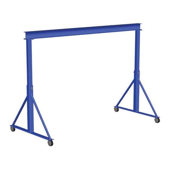
- Page 1 ® Installation, Operation, & Maintenance Manual Adjustable Height Steel Gantry Cranes IMPORTANT! DO NOT DESTROY Gorbel Customer Order No. / Serial No. ® Gorbel Dealer ® Issued: 05/2013 Revised: 09/2019 Date Month Year...
- Page 2 This page intentionally left blank.
-
Page 3: Table Of Contents
TABLE OF CONTENTS Introduction ......................Installation Step 1 - Pre-assembly ......................2 Step 2 - I-Beam to End Support Weldment Connections ...........3 Step 3 - Caster to Base Channel Connections ..............4 Step 4 - Optional Endstop/Tagline Installation ..............5 Step 5 - Final Steps ......................5 General Layout Drawings .................. -
Page 4: Introduction
INTRODUCTION Thank you for choosing a Gorbel® Gantry Crane to solve your material handling needs. The innovative design and heavy-duty construction of Gorbel® Adjustable Gantry Cranes will provide a superior quality product. All Gorbel® cranes are pre-engineered for powered hoist operation. -
Page 5: Installation Step 1 - Pre-Assembly
WARNING Gantry Crane should be used on a level, flat, smooth surface which is free of defects and obstructions. WARNING Gantry Crane should not be moved when loaded. WARNING Gantry Crane should not be moved by pushing or pulling on load. WARNING Equipment described herein is not designed for, and should not be used for, lifting, supporting or transporting humans. -
Page 6: Step 2 - I-Beam To End Support Weldment Connections
STEP 2 - I-BEAM TO END SUPPORT WELDMENT CONNECTIONS TIP: For easiest installation ensure that the end support weldments are being supported while lying on their side (as shown in Diagram 2A) prior to bolting the I-beam to them. TIP: Be sure that the top plate (located on top of vertical tubes) length is oriented parallel to the I-beam length. -
Page 7: Step 3 - Caster To Base Channel Connections
(straps/slings are preferred to reduce paint damage) that is sized and oriented correctly for raising the load) lift and rotate the Gantry Crane onto its casters by means of an overhead lifting device or lift truck. Use Gorbel® Blue touch-up paint (provided) to cover any scratches and abrasions as needed. -
Page 8: Step 4 - Optional Endstop/Tagline Installation
STEP 4 - OPTIONAL ENDSTOP/TAGLINE INSTALLATION Optional Endstop Installation (without tagline) only: Bolt the 4 endstops to I-beam (as shown in Diagram 4A) using the holes located in I-beam web. Tighten endstop hardware (refer to Chart 2A, on page 3, for proper torque rating). Optional Endstop Installation (with tagline): Bolt the 2 tagline bracket assemblies and 2 endstops to I-beam (as shown in Diagram 4B) -
Page 9: General Layout Drawings
GENERAL LAYOUT DRAWINGS 9/19... -
Page 10: Crane Operator Instructions
ANY SAFETY FEATURES AND MECHANISMS BUILT-IN OR OTHERWISE PROVIDED WITH THE CRANE BY GORBEL ARE REQUIRED FOR THE SAFE OPERATION OF THE CRANE. -
Page 11: Limited Warranty
Purchaser or end user shall be solely responsible for all freight and transportation costs incurred in connection with any warranty work provided by Gorbel hereunder. Gorbel will not be liable for any loss, injury or damage to persons or property, nor for damages of any kind resulting from failure or defective operation of any materials or equipment furnished hereunder. -
Page 12: Inspection And Maintenance Schedule
INSPECTION AND MAINTENANCE GORBEL® GANTRY CRANE INSPECTION AND MAINTENANCE SCHEDULE ITEM COMPONENT MAINTENANCE FREQUENCY* Check for full compression of lockwasher. Bolts should be Every 1,000 hours Top Plate Hardware tightened to torque specifications (Chart 2A, page 3). or 6 months Check for full compression of lockwasher.
Need help?
Do you have a question about the Adjustable Gantry Crane and is the answer not in the manual?
Questions and answers