Table of Contents
Advertisement
Quick Links
Advertisement
Table of Contents

Subscribe to Our Youtube Channel
Summary of Contents for Multitech QuickCarrier USB MT100UCC Series
- Page 1 QuickCarrier™ USB MT100UCC Developer’s Guide...
- Page 2 Copyright and Technical Support USB Card Carrier Developers Guide MT100UCC-G2, MT100UCC-H5, MT100UCC-EV2 S000513E, Revision E Copyright This publication may not be reproduced, in whole or in part, without prior expressed written permission from Multi-Tech Systems, Inc. All rights reserved. Copyright © 2013 by Multi-Tech Systems, Inc. Multi-Tech Systems, Inc.
- Page 3 Contacting Multi-Tech Knowledge Base The Knowledge Base provides immediate access to support information and resolutions for all Multi-Tech products. Visit http://www.multitech.com/kb.go. Support Portal To create an account and submit a support case directly to our technical support team, visit: https://support.multitech.com...
-
Page 4: Table Of Contents
Contents Contents Chapter 1 – QuickCarrier USB Hardware ....................7 QuickCarrier Features ........................7 Product Ordering Guide ........................7 AT Commands ..........................8 Design Considerations ........................8 USB Power Considerations ........................8 Noise Suppression Design Considerations .................... 8 PC Board Layout Guidelines ..............Error! Bookmark not defined. Mounting Hardware .......................... - Page 5 Contents Cellular Device Maintenance ....................... 17 Handling Precautions ........................... 17 Your Responsibility ..........................17 Regulatory Compliance Statements ....................18 EMC, Safety, and R&TTE Directive Compliance ................... 18 EMC Requirements for the United States ................... 18 EMC Requirements for Industry Canada ..................... 19 South African Statement ........................
- Page 6 Contents Pin-Out Specifications ........................37 Power Draw ........................... 37 Application Notes ........................... 37 LED Interface ............................37 RF Interfaces ............................38 RF Performances ..........................38 QuickCarrier Developer’s Guide...
-
Page 7: Chapter 1 - Quickcarrier Usb Hardware
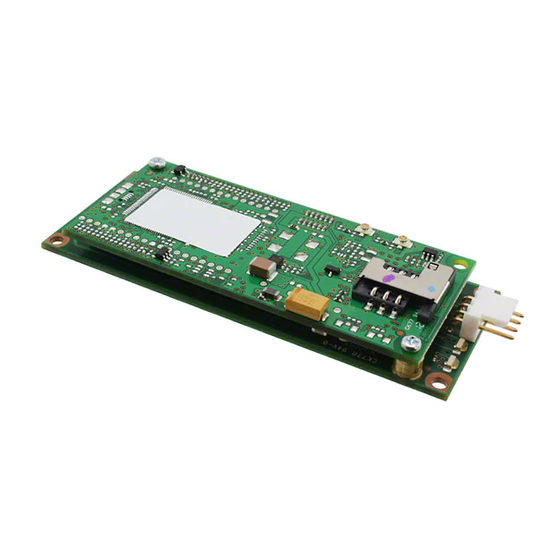
Chapter 1 – QuickCarrier USB Hardware Chapter 1 – QuickCarrier USB Hardware The QuickCarrier USB is a complete, ready-to-integrate communications device that offers 2G and 3G cellular connectivity options. These quick-to-market devices combine a network approved cellular SocketModem® and a USB carrier card in one compact design. With its 4-pin USB interface the QuickCarrier USB embedded cellular modem cables to an existing device’s internal USB port and can be secured using the four mounting holes located at the corners of the printed circuit board. -
Page 8: At Commands
CDMA 1xEV-D0 AT Commands Reference Guide (S000482) MT100UCC-EV2-N3 MT100UCC-EV2-N16 MT100UCC-H5 H5 AT Commands Reference Guide (S000574) All reference guides are available: ● By email request to oemsales@multitech.com. ● By using the Embedded Products Developer’s Guide Request Form on Multi-Tech's website. Design Considerations USB Power Considerations ●... -
Page 9: Mounting Hardware
Chapter 2 – QuickCarrier USB GPRS (MT100UCC-G2) Proper PC board layout (component placement, signal routing, trace thickness and geometry, etc.) component selection (composition, value, and tolerance), interface connections, and shielding are required for the board design to achieve desired modem performance and to attain EMI certification. Other aspects of proper noise-suppression engineering practices are beyond the scope of this developer’s guide. -
Page 10: Cellular Information
Chapter 2 – QuickCarrier USB GPRS (MT100UCC-G2) Multi-Tech Systems, Inc. strives to follow all of these recommendations. Input protection circuitry has been incorporated into the Multi-Tech devices to minimize the effect of this static buildup, proper precautions should be taken to avoid exposure to electrostatic discharge during handling. Multi-Tech uses and recommends that others use anti-static boxes that create a faraday cage (packaging designed to exclude electromagnetic fields). -
Page 11: Antenna Specifications
Chapter 2 – QuickCarrier USB GPRS (MT100UCC-G2) Antenna Specifications EV-DO, CDMA Antenna Requirements/Specifications Category Description Frequency Range 824 – 894 MHz / 1850 – 1990 MHz Impedance 50 Ohms VSWR VSWR shall not exceed 2.0:1 at any point across the bands of operation Typical Radiated Gain Requirements 0 / 2 dBi on azimuth plane (to meet PTCRB) -
Page 12: Coax Cables Specifications
Chapter 2 – QuickCarrier USB GPRS (MT100UCC-G2) GSM Antenna Requirements/Specifications Category Description Frequency Range 824 – 960 MHz / 1710 – 1990 MHz Impedance 50 Ohms VSWR VSWR shall not exceed 2.0:1 at any point across the bands of operation Typical Radiated Gain Requirements 0 / 2 dBi on azimuth plane (to meet PTCRB) -
Page 13: Oem Integration
Chapter 2 – QuickCarrier USB GPRS (MT100UCC-G2) OEM Integration FCC Grant Notes The OEM should follow all the grant notes listed below. Otherwise, further testing and device approvals may be necessary. The antenna gain, including cable loss, for the radio you are incorporating into your product design must not exceed the requirements at 850 MHz and 1900 MHz as specified by the FCC grant for mobile operations and fixed mounted operations as defined in 2.1091 and 1.1307 of the FCC rules for satisfying RF exposure compliance. -
Page 14: Fcc Definitions
However, before you can begin to use the modem, you must set up a cellular data account with your cellular network provider. Please refer to Multi-Tech’s Cellular Activation Web site http://www.multitech.com/activation.go for information on activating your cellular modem. ESN, IMEI Information The cellular carrier will ask you for device identification information: ●... -
Page 15: Modem Label Example
Chapter 2 – QuickCarrier USB GPRS (MT100UCC-G2) Modem Label Example Note: The label is shown larger than actual size. Multi-Tech Model Identification ESN (EV2) or IMEI (H5/G2) QuickCarrier USB Label Note: The label is shown larger than actual size. Multi-Tech Model Identification Multi-Tech Ordering Part Number ESN (EV2) or IMEI (H5/GP2) for the attached modem... -
Page 16: Safety Notices And Warnings
Chapter 2 – QuickCarrier USB GPRS (MT100UCC-G2) Safety Notices and Warnings Note to OEMs: The following safety statements may be used in your final product documentation. RF Safety Remote modems are cellular devices. It is important to follow any special regulations regarding the use of radio equipment due in particular to the possibility of Radio Frequency (RF) interference. -
Page 17: Cellular Device Maintenance
Chapter 2 – QuickCarrier USB GPRS (MT100UCC-G2) ● If it is incorrectly installed in a vehicle, operating the cellular device could interfere with the correct functioning of vehicle electronics. Only qualified personnel should install the device. The installation process should verify that vehicle electronics are protected from interference. ●... -
Page 18: Regulatory Compliance Statements
Chapter 2 – QuickCarrier USB GPRS (MT100UCC-G2) Regulatory Compliance Statements EMC, Safety, and R&TTE Directive Compliance Some models have received CE certification. If you need CD compliance, check with your sales representative. The CE mark is affixed to this product to confirm compliance with the following European Community Directives: ●... -
Page 19: Emc Requirements For Industry Canada
Chapter 2 – QuickCarrier USB GPRS (MT100UCC-G2) EMC Requirements for Industry Canada This Class B digital apparatus meets all requirements of the Canadian Interference-Causing Equipment Regulations. Cet appareil numérique de la classe B respecte toutes les exigences du Règlement Canadien sur le matériel brouilleur. -
Page 20: Waste Electrical And Electronic Equipment Statement
Chapter 2 – QuickCarrier USB GPRS (MT100UCC-G2) Waste Electrical and Electronic Equipment Statement Note to OEMs: This statement is included for your information. You can use it in your final product documentation. WEEE Directive The WEEE directive places an obligation on EU-based manufacturers, distributors, retailers, and importers to take-back electronics products at the end of their useful life. -
Page 21: Restriction Of The Use Of Hazardous Substances (Rohs)
Chapter 2 – QuickCarrier USB GPRS (MT100UCC-G2) Restriction of the Use of Hazardous Substances (RoHS) Multi-Tech Systems, Inc. Certificate of Compliance 2011/65/EU Multi-Tech Systems confirms that its embedded products comply with the chemical concentration limitations set forth in the directive 2011/65/EU of the European Parliament (Restriction of the use of certain Hazardous Substances in electrical and electronic equipment - RoHS) These Multi-Tech products do not contain the following banned chemicals ●... -
Page 22: Chapter 2 - Quickcarrier Usb Gprs (Mt100Ucc-G2)
Chapter 2 – QuickCarrier USB GPRS (MT100UCC-G2) Chapter 2 – QuickCarrier USB GPRS (MT100UCC-G2) The QuickCarrier USB GPRS is an embedded USB cellular modem that offers standards-based quad-band GSM/GPRS Class 10 performance. These quick-to-market devices combine a network approved cellular SocketModem and a USB carrier card in one compact design. - Page 23 Chapter 2 – QuickCarrier USB GPRS (MT100UCC-G2) Category Description Compliance EMC Compliance FCC Part 15 Class B EN55022 EN55024 Radio Compliance FCC Part 22 FCC Part 24 RSS 132 RSS 133 EN 301 511 EN 301 489-1 EN 301 489-7 Safety Compliance UL 60950-1 2 cUL 60950-1 2...
-
Page 24: Mechanical Drawing
Chapter 2 – QuickCarrier USB GPRS (MT100UCC-G2) Mechanical Drawing QuickCarrier Developer’s Guide... -
Page 25: Pin-Out Specifications
Chapter 2 – QuickCarrier USB GPRS (MT100UCC-G2) Pin-Out Specifications Pin(s) Signal Name Logic Level Voltage Description JP2-1 DC input power JP2-2 USB DN USB data JP2-3 USB DP USB data JP2-4 Ground Power Draw Multi-Tech Systems, Inc. recommends that you incorporate a 10% buffer into your power source when determining product load. -
Page 26: Rf Performances
1 = Modem restarts immediately using the specified band(s). For example, type AT+WMBS=4,0 and press Enter. For additional band settings and information, refer to GPRS AT Commands for Multi-Tech G2 Cellular Modems (S000463). To request this document, contact oemsales@multitech.com. QuickCarrier Developer’s Guide... -
Page 27: Chapter 3 - Quickcarrier Usb Hspa (Mt100Ucc-H5)
Chapter 3 – QuickCarrier USB HSPA (MT100UCC-H5) The QuickCarrier USB HSPA is an embedded USB cellular modem uses HSPA technology to deliver some of the fastest cellular data speeds. These quick-to-market devices combine a network approved cellular SocketModem and a USB carrier card in one compact design. With its 4-pin USB interface the QuickCarrier USB embedded cellular modem cables to an existing device’s internal USB port and can be secured using the four mounting holes located at the corners of the printed circuit board. - Page 28 Chapter 3 – QuickCarrier USB HSPA (MT100UCC-H5) Category Description Compliance EMC Compliance FCC Part 15 Class B EN 55022 Class B EN 55024 Radio Compliance FCC Part 22 FCC Part 24 RSS 132 RSS 133 EN 301 511 EN 301 489-1 EN 301 489-7 EN 301 489-24 Safety Compliance...
-
Page 29: Mechanical Drawing
Chapter 3 – QuickCarrier USB HSPA (MT100UCC-H5) Mechanical Drawing QuickCarrier Developer’s Guide... -
Page 30: Pin-Out Specifications
Chapter 3 – QuickCarrier USB HSPA (MT100UCC-H5) Pin-Out Specifications Pin(s) Signal Name Logic Level Voltage Description JP2-1 DC input power JP2-2 USB DN USB data JP2-3 USB DP USB data JP2-4 Ground Power Draw Multi-Tech Systems, Inc. recommends that you incorporate a 10% buffer into your power source when determining product load. -
Page 31: Powering Down Your Device
Chapter 3 – QuickCarrier USB HSPA (MT100UCC-H5) Radio IP Connection to Agilent with Data Peak TX Peak Peak Protocol Amplitude Reset Reset Current Current Current Low Power Half Power Max Power (Amps) (InRush) (InRush) 577uS (Amps) Duration Measured MS Transmit (GSM) Xmit Measured MS Xmit... -
Page 32: Application Notes
Chapter 3 – QuickCarrier USB HSPA (MT100UCC-H5) Application Notes LED Interface The LED signal indicates the working status of the QuickCarrier. Power LED Signal Description No power to the unit The unit is functioning Link Status LED Signal Description No power to the unit Continuously lit Powered and connected, but not transmitting or receiving. -
Page 33: Frequency Bands Supported
Chapter 3 – QuickCarrier USB HSPA (MT100UCC-H5) Category Description Maximum output power (UMTS Band I 2100) +23 dBm ± 1 dBm (class 3) RF Connection and Antenna The RF connector on the QuickCarrier is a UFL standard type. See Chapter 1 for Antenna details. -
Page 34: Chapter 4 - Quickcarrier Usb Ev-Do (Mt100Ucc-Ev2)
Chapter 4 – QuickCarrier USB EV-DO (MT100UCC-EV2) The QuickCarrier USB EV-DO embedded cellular modems are 3G modules supporting CDMA EV-DO Rev A and below. These devices combine a network approved cellular SocketModem and a USB carrier card in one compact design. QuickCarrier USB EV-DO modems are equipped with dual-band 800/1900 MHz bands with receive diversity support on both bands. - Page 35 Chapter 4 – QuickCarrier USB EV-DO (MT100UCC-EV2) Category Description Point-to-Point messaging Mobile-Terminated SMS Mobile-Originated SMS Compliance EMC Compliance FCC Part 15 Class B Radio Compliance FCC Part 22 FCC Part 24 Safety Compliance UL 60950-1 2 cUL 60950-1 2 IEC 60950-1 2 Network Compliant Socket Modem Verizon Sprint...
-
Page 36: Mechanical Drawing
Chapter 4 – QuickCarrier USB EV-DO (MT100UCC-EV2) Mechanical Drawing QuickCarrier Developer’s Guide... - Page 37 Chapter 4 – QuickCarrier USB EV-DO (MT100UCC-EV2) Pin-Out Specifications Pin(s) Signal Name Logic Level Voltage Description JP2-1 DC input power JP2-2 USB DN USB data JP2-3 USB DP USB data JP2-4 Ground Power Draw Multi-Tech Systems, Inc. recommends that you incorporate a 10% buffer into your power source when determining product load.
- Page 38 Chapter 4 – QuickCarrier USB EV-DO (MT100UCC-EV2) RF Interfaces Radio Characteristics CDMA/EV-DO 800 CDMA/EV-DO 1900 Frequency RX 869 to 894 MHz 1930 to 1990 MHz Frequency TX 824 to 849 MHz 1850 to 1910 MHz Impedance 50 ohms VSWR <2 Typical Radiated Gain 0 dBi in at least one direction Output Power...
Need help?
Do you have a question about the QuickCarrier USB MT100UCC Series and is the answer not in the manual?
Questions and answers