Advertisement
Quick Links
Total solder points: 187
Difficulty level:
beginner 1o 2þ 3o 4o
5oadvanced
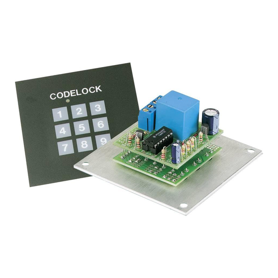
Code Lock
K6400
Features
þ More than 3000 codes possible.
þ State indication by LED.
þ Pulse or switch output.
þ Nine digits of which 4 code digits.
þ Secured against polarity reversal.
specifications :
• Power supply : 9 to 15VDC or 8 to 12VAC.
• Relay output : 5A / 220V.
• Time limit for code determination : +/- 5sec.
• Current consumption : Output OFF : 0,3µA
Output ON : 40mA
ILLUSTRATED ASSEMBLY MANUAL
H6400IP-2
Advertisement

Related Manuals for Velleman Velleman-Kit K6400


Summary of Contents for Velleman Velleman-Kit K6400
- Page 1 Total solder points: 187 Difficulty level: beginner 1o 2þ 3o 4o 5oadvanced Code Lock K6400 Features þ More than 3000 codes possible. þ State indication by LED. þ Pulse or switch output. þ Nine digits of which 4 code digits. þ...
- Page 2 VELLEMAN Components NV Legen Heirweg 33 9890 Gavere Belgium http://www.velleman.be http://www.velleman-kit.com...
- Page 3 Assembly hints 1. Assembly (Skipping this can lead to troubles ! ) Ok, so we have your attention. These hints will help you to make this project success- ful. Read them carefully. 1.1 Make sure you have the right tools: •...
- Page 4 Assembly hints 1.3 Soldering Hints : Mount the component against the PCB surface and carefully solder the leads Make sure the solder joints are cone-shaped and shiny Trim excess leads as close as possible to the solder joint AXIAL COMPONENTS ARE TAPED IN THE CORRECT MOUNTING SEQUENCE ! REMOVE THEM FROM THE TAPE ONE AT A TIME !
- Page 6 Construction This code lock can be used to switch an alarm (e.g. car alarm K3504) on and off as well as to open a door lock. A LED on the operation panel reflects the state of the "lock". You can easily determine the code yourself.
- Page 7 The code Determining the code The four code digits are determined by fitting wire jumpers, see figure 1.0. Drawing 1.1 shows the connections for code 1234 as an example. Attention : the wire jumpers that build the code must be as close to the pcb as possible, because other- wise they will touch the aluminium front panel! The code sequence is determined by connecting the lines A, respectively B, C and D to the connecting terminals...
- Page 8 Preparation Preparation Fit seven non insulated wires at the solder side of the pcb. These wires will be used later on for through connection to the master module (see fig. 2.0). Attention : the wires at the component side must be cut off as close to the pcb as possible.
- Page 9 Construction Construction of P6400B 1. Jumpers on/off function of the key lock. q J1 Fit wire jumper J1 in case you intend to use the on/off function of the key lock. If you don't fit this wire jumper, then, at the input of the code, the code lock will only generate a pulse (in general this mode is used with door locks).
- Page 10 Construction 2. Resistors. 5. Transistors. R... q R8 : 10 (1-0-0-B) q T1, T2 : BC547B or eq q R9 : 220 (2-2-1-B) q R11 : 1K5 (1-5-2-B) 6. Resistors. 3. Diodes R... D... CATHODE q R1: 470K (4-7-4-B) q R2...R4 : 47K (4-7-3-B) q D1 : 1N4148 or eq.
- Page 11 Construction 8. Screw connector q J2 : 2 x 2p 9. Relay q RY1 : VR15M121C 10. IC , Check the position of the notch ! q IC1: CD4066...
- Page 12 Assembly Assembly (fig 3.0) CHECK THE WHOLE MOUNTING ONCE MORE THOROUGHLY AND DON'T FOR- GET THE CODE, BECAUSE AFTER THE FOLLOWING ASSEMBLY IT WON'T BE ACCESSIBLE ANY MORE. Pass two 2mm bolts through the front panel and fix them using a nut. Then pass a lock washer over the bolts fol- lowed by the keyboard module.
- Page 13 Test & building in Test and Usage Connect a 9 to 15VDC or a 8 to 12VAC to the points V and GND. (V is the plus pole in the case of direct current). Put the front panel film next to the keyboard and enter the right code (in the case of a pulse output this has to be done within 5 seconds).
- Page 14 PCB layout P6400S - Keyboard P6400B - master...
- Page 15 Diagram Schematic diagram.
- Page 16 VELLEMAN Components NV Legen Heirweg 33 9890 Gavere Belgium Europe http://www.velleman.be http://www.velleman-kit.com Modifications and typographical errors reserved © Velleman Components nv. H6400IP - 2001 - ED2...
Need help?
Do you have a question about the Velleman-Kit K6400 and is the answer not in the manual?
Questions and answers