
Summary of Contents for DI-BOX FLOWBOX
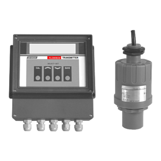
- Page 1 Flow meter: ULTRASONIC FLOW METER FLOWBOX Rising element: PALMER-BOWLUS FLUME ZPB160 User’s manual FLOWBOX TRANSMITTER Wrocław 2020...
- Page 2 B class. This manual was issued only in order for information purposes. All information included can be changed. The DI-BOX does not bear the responsibility for any direct and indirect defects arisen as a result of using this manual.
-
Page 3: Table Of Contents
5.1. Technical data ................5.2. Installation and launch of the MODBUS interface ....... 5.3. Description of registers of the transmitter M1600 ......6. MAINTENANCE RECOMMENDATIONS ............6.1. Palmer-Bowlus ZPB flume ultrasonic sensor SPA 380-4 ......Copyright © DI-BOX 2020, www.di-box.com.pl, info@di-box.com.pl... -
Page 4: Initial Information
In the scope of this application, the FLOWBOX flow meter determines the temporary flow on the basis of liquid accumulation in the Palmer-Bowlus flume ZPB160, in accordance with the guidelines and recommendations of the ISO 4359:1983 standard. -
Page 5: Ultrasound Level Sensor Spa 380-4
The basic usage is situated at measuring level in industrial and municipal sewage treatment plants, batch and reserve tanks, wells, sewage wet wells, measuring instruments in open channels, etc. Copyright © DI-BOX 2020, www.di-box.com.pl, info@di-box.com.pl... -
Page 6: Palmer Bowlus Zpb Flume
It is recommended to gravitation channels with circular section and pipelines working without pressure. The channel assures exact relation between the level of its filling and liquid flow intensity in the channel or pipeline. Copyright © DI-BOX 2020, www.di-box.com.pl, info@di-box.com.pl... - Page 7 Ø 250 Ø 800 ZPB250 1190 ZPB800 1700 2600 Ø 315 Ø 1000 ZPB300 1400 ZPB1000 4380 1050 3500 In order to obtain the proper flow intensity, the flume must be installed horizontally without fall. Copyright © DI-BOX 2020, www.di-box.com.pl, info@di-box.com.pl...
-
Page 8: Installation Of Measuring Set
The way of ultrasonic signal should be free of any disturbances. → The surface of the assembly should be free of vibrations. → The surrounding temperature should be between -20˚C..+70˚C → There should not be the electric power cables or electric power converters nearby. Copyright © DI-BOX 2020, www.di-box.com.pl, info@di-box.com.pl... - Page 9 All connections of electric wires should be placed as to prevent from their mechanical damage. → The installation of the device must meets with electromagnetic compatibility rules. → The influence of the disturbances of the other devices on the flow meter work must be strictly eliminated! Copyright © DI-BOX 2020, www.di-box.com.pl, info@di-box.com.pl...
-
Page 10: Connecting The Wires To The Transmitter M1600
Do not touch the strip joints while making the connection of the wires to the terminal strips (use the screwdrivers with the isolations, hang the wires on isolation). Unscrew and take off a cover Copyright © DI-BOX 2020, www.di-box.com.pl, info@di-box.com.pl... -
Page 11: Scheme Of Electric Connections Of The Transmitter M1600
Resistor should limit a current to max 150mA. For PLC R = ~ 2-3kΩ. Installation of the device must meets the electromagnetic compatibility rules. The influence of the disturbances of the other devices on the flowmeter work must be strictly eliminated! Copyright © DI-BOX 2020, www.di-box.com.pl, info@di-box.com.pl... -
Page 12: Device Service
4.2. In the event of change the sensor or measuring flume the M1600 transmitter should be programmed in the company DI-BOX. 4.1. Display of device The four-buttons keyboard and liquid-crystal unit are to communicate with the user. -
Page 13: Device Calibration
After proper installation of measuring set you should make the measurement of the setting of ultrasound sensor SPA 380-4 with relation to the measuring feet of ZPB 160 flume and enter into the memory of the M1600 transmitter. Copyright © DI-BOX 2020, www.di-box.com.pl, info@di-box.com.pl... - Page 14 If there is not possible to perform the above-mentioned procedure for some reasons, applying the solution with lower exactness - physically measure the distance front sensor from measuring feet. In order to change the setting the following should be performed: Copyright © DI-BOX 2020, www.di-box.com.pl, info@di-box.com.pl...
-
Page 15: Measuring Scope And Input Electric Current Set
4.3. Measuring scope and input electric current set Wanting to read out or set the measuring scope or outflow current, one should: → Press the button SAVE through about 5 seconds until the announcement displays: 0.0 - 40.0 measuring scope Copyright © DI-BOX 2020, www.di-box.com.pl, info@di-box.com.pl... -
Page 16: Modbus Interface
7. Maximum access time to a single station: below 300 ms. 8. Format of transmission for a single character (asynchronous transmission): → rate: 9600 bauds, → number of bits: 8 (RTU), → number of stop bits: 1, Copyright © DI-BOX 2020, www.di-box.com.pl, info@di-box.com.pl... -
Page 17: Installation And Launch Of The Modbus Interface
SAVE key, → pressing CAL key again before pressing SAVE key will result in cancelling the carried out settings and return to the display of the current device number. Copyright © DI-BOX 2020, www.di-box.com.pl, info@di-box.com.pl... -
Page 18: Description Of Registers Of The Transmitter M1600
2 – illegal address of registers, 3 – illegal value of registers. Handling of errors in the M1600 transmitter The following messages are shown on the transmitter display: # - transmitters is connected to the Modbus network, Copyright © DI-BOX 2020, www.di-box.com.pl, info@di-box.com.pl... -
Page 19: Maintenance Recommendations
Check the permeability and clearness of the liquid piling up elements (measuring flume) depending on needs. The maintenance of the sensor SPA 380-4 refers to the occasional check of sensor surface clearness and possible wiping the sensor frontal surface with the soft cloth. Copyright © DI-BOX 2020, www.di-box.com.pl, info@di-box.com.pl...
Need help?
Do you have a question about the FLOWBOX and is the answer not in the manual?
Questions and answers