Table of Contents
Advertisement
Quick Links
The information in this document has been carefully checked and is believed to be entirely reliable. However, no
responsibility is assumed for inaccuracies. Furthermore, Cyclone Microsystems, Inc. reserves the right to make
changes to any products herein to improve reliability, function, or design. Cyclone Microsystems, Inc. neither
assumes any liability arising out of the application or use of any product or circuit described herein, nor does it
convey any license under its right or the rights of others.
PCIE2-2711
PCIE GEN2
EXPANSION SYSTEM
USER'S MANUAL
Revision 1.1, October 2017
Cyclone P/N 800-2711
Copyright 2017 by Cyclone Microsystems, Inc.
Advertisement
Table of Contents

Summary of Contents for CyClone PCIe2-2711
- Page 1 Furthermore, Cyclone Microsystems, Inc. reserves the right to make changes to any products herein to improve reliability, function, or design. Cyclone Microsystems, Inc. neither assumes any liability arising out of the application or use of any product or circuit described herein, nor does it convey any license under its right or the rights of others.
-
Page 2: Table Of Contents
PCIe-436 Mechanical ......................4-3 4.4.3 PCIe-436 LED Indicators.....................4-3 4.4.4 PCIe-436 Output Swing, De-Emphasis and Receive Equalization........4-3 LINK INDICATION - LED DEFINITION PCIe-460 ................4-3 SYSTEM MONITOR BOARD ......................4-4 CHAPTER 5 PHYSICAL CONFIGURATION......................5-1 PCIe2-2711 PCI Express Gen2 Expansion System User’s Manual Revision 1.1, October 2017... - Page 3 PCIe2-460 Power Requirements..................3-3 Table 3-5 PCIe2-426 Power Requirements..................3-4 Table 3-6 Power Supplied Per PCIe Slot.....................3-4 Table 4-1 PCIe2-426 Default DIP Switch Configuration ..............4-2 Table 4-2 Link LED Indication......................4-4 PCIe2-2711 PCI Express Gen2 Expansion System User’s Manual Revision 1.1, October 2017...
-
Page 4: Chapter 1 Introduction
77 CFM fans. The PCIe2-2711 is available with either a 3240 W or 2180 W N+1 redundant power supply in a 5U chassis, or a 1200 W standard ATX supply in a 4U chassis. -
Page 5: Figure 1-1. Pcie2-2711 Block Diagram
PCIe2 x16 Slot PCIe2 Slot Swi t ch x16 Gen2 PCIe2 x16 Slot 96 Lanes x16 Gen2 PCIe2 x16 Slot x16 Gen2 PCIe2 x16 Slot Figure 1-1. PCIe2-2711 Block Diagram PCIe2-2711 PCI Express Gen2 Expansion System User’s Manual Revision 1.1, October 2017... -
Page 6: Specifications
INTRODUCTION SPECIFICATIONS The specifications in Table 1-1 detail the PCIe2-2711 Expansion System chassis including the PCIe-460 expansion backplane, PCIe-436 Upstream Cable Adaptor and chassis/power supply. The chassis also includes four 77 CFM fans. Table 1-1. Physical/Environmental Characteristics Height 8.75 inches (5U Chassis) -
Page 7: Standards
Output Current Output Current +12V -12V +3.3V +5VSB STANDARDS PCI Express Base Specification Revision 2.0 PCI Express Card Electro Mechanical Specification 2.0 PCI Express External Cabling Specification 2.0 PCIe2-2711 PCI Express Gen2 Expansion System User’s Manual Revision 1.1, October 2017... -
Page 8: Ordering Information
O: No Monitoring Board Z: PCIe Cable Width Option A: x16 PCIe Cabling (Includes PCIe2-426, PCIe2-436 and x16 Cable) B: x8 PCIe Cabling (Includes PCIe2-425, PCIe2-439 and x8 Cable) PCIe2-2711 PCI Express Gen2 Expansion System User’s Manual Revision 1.1, October 2017... -
Page 9: Chapter 2 Theory Of Operation
AC power outlet and any desired add-in cards are installed, the system is ready to be turned on. When a host is turned on, a signal from the PCIe-426 will turn on the PCIe2-2711 chassis. When two hosts are used, the first host on will turn the system on and the last host off will turn the system off. -
Page 10: Chapter 3 Pcie2-2711 Chassis
SEATING OF CARDS Unlike standard PC applications, the PCIe2-2711 Expansion Systems has a narrow lower gate that precisely engages the lower end of the PCI Express Add-In board’s face panel. The purpose is to ensure correct electrical connector mating of up-plugged boards. -
Page 11: Chassis Cooling
EXPANSION CHASSIS CHASSIS COOLING Airflow in the PCIe2-2711 chassis is provided by four 77 CFM fans located midship across the full width of the chassis. CHASSIS POWER There are three different power supply options available for the PCIe2-2711. The 1200W option provides ample power for the backplane and low-powered PCIe devices. -
Page 12: Power Considerations
0.5A per jumper. POWER CONSIDERATIONS Table 3-4 through 3-6 show the power consumption for the Cyclone Microsystems boards and the power supplied to PCI Express slots. Note that the PCIe-426 is installed in and powered by the host supply. -
Page 13: Pci-E Auxilary Power Connectors
The power supply in the expansion chassis has at least eight PCIe auxilary power cables labeled “PCI-E” available for these card types. GPU card users should verify that all external power connections to their cards have been made. PCIe2-2711 PCI Express Gen2 Expansion System User’s Manual Revision 1.1, October 2017... -
Page 14: Chapter 4 System Power Up
The green LED indicates that the chassis is powered. If two host PCs are connected to the PCIe2-2711, then the first host to power up turns on the system. The last host to power down turns off the system. -
Page 15: Pcie2-426 Led Indicators
Microsystems has determined is the best setting for Gen1 or Gen2 operation with both the 1m and 3m PCIe cables shipped with Cyclone PCIe Expansion systems. Users should not change the DIP switch settings unless they have the proper test equipment to verify their results. Users change de-emphasis, output swing and receive equalization at their own peril. -
Page 16: Pcie-436 Mechanical
The as-shipped-default configuration of the transceiver silicon is what Cyclone Microsystems has determined is the best setting for Gen2 operation with both 1m and 3m PCIe cables shipped with Cyclone PCIe Expansion systems. This configuration will also function adequately for Gen1 operation. -
Page 17: System Monitor Board
SYSTEM MONITOR BOARD The PCIe2-2711 system has an optional System Monitor board. It has the same outline and profile as a x1 PCI Express add-in card but it is not, it has a proprietary pin out and should be installed ONLY in slot J9 of the PCIe-460. -
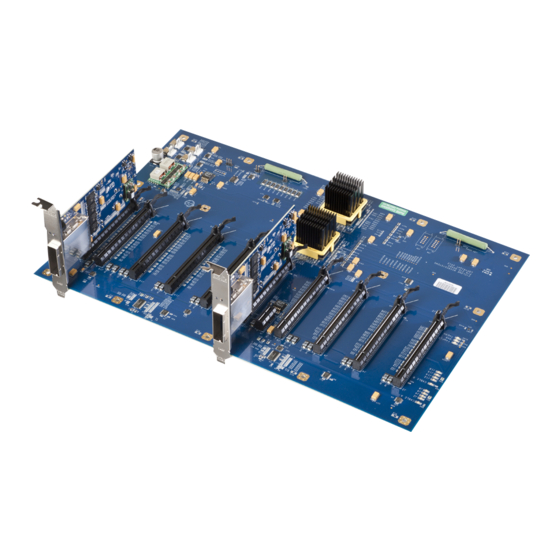
Page 18: Physical Configuration
Figure 5-1 is a physical diagram (not to scale) of the PCIe-460 backplane, showing the location designators of jumpers, connectors, and major ICs. Refer to this figure when component locations are referenced in the manual text. PCIe2-2711 PCI Express Gen2 Expansion System User’s Manual Revision 1.1, October 2017... - Page 19 PHYSICAL CONFIGURATION Expansion System Signal Detect LED Expansion System Present LED Figure 5-2. PCIe-426 LEDs Figure 5-3. PCIe-426 Physical Configuration PCIe2-2711 PCI Express Gen2 Expansion System User’s Manual Revision 1.1, October 2017...
-
Page 20: Figure 5-4 Pcie-436 Leds
PHYSICAL CONFIGURATION Figure 5-4. PCIe-436 LEDs Expansion System Signal Detect LED Expansion System Present LED Figure 5-5. PCIe-436 Physical Configuration PCIe2-2711 PCI Express Gen2 Expansion System User’s Manual Revision 1.1, October 2017... -
Page 21: Figure 5-6 Pcie2-2711 5U Chassis
PHYSICAL CONFIGURATION Figure 5-6. PCIe2-2711 5U Chassis PCIe2-2711 PCI Express Gen2 Expansion System User’s Manual Revision 1.1, October 2017...
Need help?
Do you have a question about the PCIe2-2711 and is the answer not in the manual?
Questions and answers