Advertisement
Quick Links
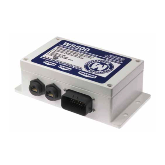
Wakespeed's WS500 Advanced Alternator Regulator provides
onboard support for multiple battery technologies, via selectable
DIP switches, including standard flooded (thin plate) and deep
cycle flooded, Gel, standard AGM, carbon foam AGM (Firefly),
high-density AGM, and LiFePO4.
In addition, the WS500 offers the ability to upload pre-engineered
configuration files for a growing number of battery brands and
chemistries, based on the battery manufacturer's charging
recommendations by using the Wakespeed File Transfer Utility.
With the use of a Windows PC and a Micro USB cable, these
configuration files are downloadable from the Wakespeed website,
and uploaded to the WS500 Regulator. Configuring the regulator
does not require that the WS500 is installed in the vehicle or
vessel. Software and firmware upgrades can be done at the
workbench or at the dining table, as well as in place.
The following guide is designed to walk the installer or end user
through the upgrade/configuration process.
These items are necessary for the upgrade process:
• Windows-based computer with available USB port
• Access to the internet to download configuration .ZIP files
• High-quality Micro-USB cable
• Phillips hand or cordless screwdriver
• A non-metallic tool for depressing RESET button (doweling or
end of a pen or unsharpened pencil work well) is helpful
© 2020 Thomason Jones Co. LLC (Wakespeed Offshore)
Advertisement

Summary of Contents for Wakespeed Offshore WS500
- Page 1 Wakespeed website, and uploaded to the WS500 Regulator. Configuring the regulator does not require that the WS500 is installed in the vehicle or vessel. Software and firmware upgrades can be done at the workbench or at the dining table, as well as in place.
-
Page 2: Getting Started
For the sake of illustration, we’ll look at a configuration update file from the Wakespeed website. Configuration files are accessed on the website’s Technical page (www.wakespeed.com/technical.html). Under the table header “WS500 Configuration Files” is a list of available files, broken down by manufacturer and product series. - Page 3 Remove the regulator’s lid and place out of the way. The open regulator box will provide access to the micro USB port and RESET button. The USB connector is scaled for use with a standard Micro USB cable, like one would use with an Android smartphone.
- Page 4 Figure 6 — Close-up of contents in the Configuration folder Figure 7 — Micro USB connector & reset button Figure 8 — Micro USB cable connected See instructions for customizing battery profiles starting on Page 7.
- Page 5 cable will provide power for the regulator’s processor during the configuration process. 5. The configuration program will update the regulator’s firmware before installing the configuration files. To start the firmware upgrade, press and hold the reset button for five seconds and release.
- Page 6 modifying the configuration Program While the downloaded .ZIP file is designed to fit a broad range of applications, there may be certain values that the installer or user may want to modify. The following instructions are intended to provide guidelines for some of the more commonly changed values, additional information is provided in the communication and Programming guide that’s available at www.wakespeed.com/technical.html.
-
Page 7: Modifying A Configuration File
The configuration text file contains a string of command lines; each that modifies the behavior of the WS500 to optimize control of the alternator to match the needs of the batteries and charging system. The .txt file shown in Figure 12 is a good example of a typical configuration file. In most cases, the file will provide all the settings the regulator requires to provide a safe, effective profile for charging. - Page 8 translating the .txt Profile When opened in a terminal program or text editor, the Lifeline Standard AGM program will appear as follows: # LIFELINE AGM config file Based on details in: Lifeline Technical Manual, rev E Date: 3/17/2020 Lifeline standard 100c alternator # Lifeline AGM $SCA: 0,100,1.00,0.75,0.50,0,0,0,10000,0,0,30,0@...
- Page 9 shunt reversal – Allows user to compensate if a shunt is installed backward. “0” is normal polarity. “1” will reverse the polarity of the readings. idle rPms – Used in conjunction with Pull Back Factor (PBF). Determined in whole numbers (0 1500). Default zero setting enables regulator to automatically deter- mine idle RPM.
- Page 10 4. exit VBat – Represents the minimum amperage allowed before regulator advances from acceptance to over-charge. Range is floating point numbers 0.0 20.0. Setting Exit V Bat at zero will disable over-charge mode. 5. exit amps – Ranging in whole numbers from 0 50, this value will keep the regulator in over-charge until acceptance current falls to or below the set value.
- Page 11 4. exit duration – Whole number (0 600 (10 hours) controls duration regulator will remain in equalization mode, at which point the regulator will return to float voltage. “0” will disable this feature. 5. exit amps – Whole number (0 50) Controls minimum delivered current level before regulator exits equalization to float.
- Page 12 maximum charge temperature – Whole number (20 95). Charging will be discon- tinued when measured battery temperature exceeds value chosen. Measured in °C. rdc Volts – Floating point value (0.0 12.0) regulator will work in Reduced Charge mode where maximum current delivered will be limited to RDC amps. “0.0” will disable this feature.
- Page 13 3. sV override – Floating point number (0.0 4.0). This override allows the regulator to be used in other systems not supported by the auto-detect feature. To determine the SV multiplier, divide the system voltage by 12. (i.e., a 32V system would be 32/12=2.67). SV Override must be set at 0.0 to enable auto system voltage detect.
Need help?
Do you have a question about the WS500 and is the answer not in the manual?
Questions and answers