Table of Contents
Advertisement
Quick Links
Advertisement
Table of Contents

Summary of Contents for 4CR FY-3C
- Page 1 Instruction Manual 9751.0003 IR 3C...
-
Page 2: Table Of Contents
Contents 1. Precautions 2. Specifications 3. Installation 4. Controls 5. Operation 6. Troubleshooting 1) Troubleshooting 2) Light Tube Replacement 7. Exploded View 8. Circuit Diagram... -
Page 3: Precautions
1. Precaution 1. Read this manual carefully before installing or using this equipment. 2. This equipment is designed for paint drying applications. Adjust to the correct temperature and check minimum safe distance from the heat source when using. Improper use may cause paint surface damage. 3. -
Page 4: Specifications
2. Specifications FY-3 Model 220V / 1-phase / 50-60Hz Input Voltage 3 × 1000W Input Power 1200 × 1000mm Curing Area 35°C - 100°C adjustable Temperature 0min - 99min adjustable Time Setting Light Intensity 10% - 100% 2400mm 1600mm 2050mm Page 2... -
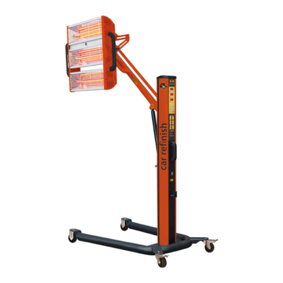
Page 5: Installation
3. Installation The shortwave infrared curing lamp is divided into 3 parts (a base, a column and a cassette). 1) Installation of the base. a. Open the packing of the base. b. Install the four wheels on the base respectively and tighten up the screws. Usually, the wheels with brakes should be mounted on the rear of the base. -
Page 6: Controls
4. Controls 1. Time display 2. Time adjustment 3. Power display AUTO 4. Power adjustment 5. Distance display 6. Distance adjustment 7. Lamp selector (each lamp can be controlled Pull-up this handle Pull-up this handle separately) for cassette moving for cassette moving up and down. -
Page 7: Operation
5. Operation 1.Automatic Mode a. Properly assemble the curing system according to the instruction (see page 3). b. Switch on the power supply. The display will go through the start-up procedure and automatically default to Automatic Mode. The system is ready to use when the parameters appears on the display screen as follows: Time to adjust 00:00... - Page 8 5. Operation 2. Manual Mode a. Press the button “Auto” to shut down the automatic mode. b. Press the button to select "Routine" or "Pulse”. c. Press the button "Start". d. The curing distance between the cassette and paint surface should be set according to the paint material and weather(air humidity).
-
Page 9: Troubleshooting
6. Troubleshooting 1. Troubleshooting PROBLEM CAUSE SOLUTION Light tube does not work a. Light tube damaged a. Check light tube b. Lamp is not plugged in b. Check the connections c. Control silicon damaged c. Check control silicon Light tube does not turn a. -
Page 10: Light Tube Replacement
6. Troubleshooting 2. Light Tube Replacement Prepare the cassette which needs replacement. b. Remove the grille of cassette. c. Remove the plates from both ends of the cassette. d. Remove the fixed plates from both ends of the cassette. e. Loosen fixed screws and cut off connections, the light tube can be replaced. -
Page 11: Exploded View
7. Exploded View NAME NAME NAME NAME Upright post Plastic nut Front caster Transformer Top cover Connecting axle U-type base Cover plate (upper) Plastic band Connector (right) Back wheel Circuit board Connector (left) Handle Cover plate (lower) Bracket Lower support arm Flange Clamping bar Upper support arm... -
Page 12: Circuit Diagram
8. Circuit Diagram Control Trans form ers Pow er Sw itch AC 220V Distance Board Page 10...
Need help?
Do you have a question about the FY-3C and is the answer not in the manual?
Questions and answers