Table of Contents
Advertisement
Quick Links
Advertisement
Table of Contents

Summary of Contents for ANTONUS STEP BROTHER
- Page 1 USER MANUAL STEP BROTHER...
- Page 2 This project is not something static and this manual will not too, so any suggestion that help improve it in future revisions will be wel- come. For any suggestion or doubt you can contact us through the following channels: Email: info@antonus-synths.com Web: www.antonus-synths.com Facebook: Antonus Instagram: @antonus_synths...
- Page 3 “Argensynth” Facebook community, for all the support since the beginning of the Antonus project activities until the development and pulish of the Step Brother as well as the trust and direct support from certain members of the group have given at the time of manufac- turing the first units.
-
Page 4: Table Of Contents
IV.1. Front panel ..............11 Specifications ..............39 IV.2. Rear panel ..............14 Patch sheet ................41 Step Brother parts, descriptions and uses ....15 V.1. The sequencer ............... 15 Using the sequencer ............18 VI.1. Tuning a sequence ............18 VI.2. -
Page 5: Introduction
Introduction If you are reading this manual is because you have bought a Step Brother , which I want to thank, but you can also to be reading this just for the interest or curiosity in the instru- ment, in that case also thank too, more in today times where the sequencers catalogue is so large and varied. -
Page 6: Where We Come From
The Step Brother is founded around the classic design of interesting functions for example to define a tuned pitch ad- the ARP Sequencer, one of the first analog sequencers com- just thanks to the quantizer where the voltage output is sca- mercialy manufactured. - Page 7 But the Step Brother is not simply an ARP Sequencer re- not only aesthetics differences, but also “places” where to plica and no more. The idea of the Step Brother was also de- use it. It does not mean that the ARP Sequencer could not be...
- Page 8 bution is, instead of adding, is multiplying the whole range of uses that can be provided not only to the sequencer itself, but to the 2600 or any modular system. However, the new features can be summarized from to the Arp Sequencer previous design: 1.
-
Page 9: Describing The Step Brother
II. Describing the Step Brother The Step Brother is a design made with analog technolo- the longevity and the possibility of finding answers with the gy and logical CMOS, no digital processors or a microcon- passing of many years, the idea is to avoid like some clas- trollers are involved. - Page 10 The intention with all this is Step Brother becomes an ins- trument that remain for a long time in the equipment of the musician, that its use is intense and not superficial, that mu-...
-
Page 11: Power Requirements
To prevent damage avoid to be used in places where water or rain can acces inside the unit. You have to be careful with using or putting the Step Brother in places where there is a AC outlet with On-Off switch and main fuse located at rear of the instrument. -
Page 12: Panel Description
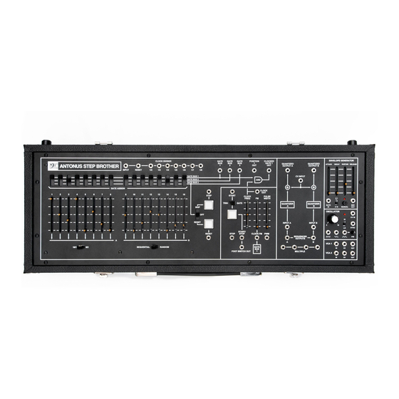
CLOCK DIVIDER GATE GATE GATE POSITION CLOCKED GATE 1 QUANTIZED QUANTIZED SUSTAIN RELEASE ATTACK DECAY ANTONUS STEP BROTHER OUTPUT A OUTPUT B INPUT RESET GATE BUS 1 CV INPUT GATE BUS 2 GATE BUS 3 GATE ASSIGN CLOCK STEP START... - Page 13 GATE assignment switches. These switch the step GATE Quantizer inputs. When a patch cord is plugged into signal to one of three output buses. These outputs can these jacks, the connection from the sequencer outputs be connected (using patch cables) to control filters, is temporarily disconnected.
- Page 14 Gate bus outputs. Individual output of each Gate bus. Clock divider. Clock input (normalized with sequencer clock output) with division outputs and reset counter input. More details in chapter VI.10. Envelope generator, envelope trigger input and signal output. Control of attack, decay, sustain and final re- lease, time factor multiplier for short/long times.
-
Page 15: Iv.2. Rear Panel
INTERNAL CLOCK START CONTINUE STOP ADJ. START/STOP Antonus Step Brother Designed and made in Barcelona IEC power input socket. With general fuse and on / off Status output 5v for playback and 0v for stop. switch. Pedal input. MIDI Input. -
Page 16: Step Brother Parts, Descriptions And Uses
Find the area of the front panel that has the three slide synthesizer (at least in theory, with the Step Brother we will controls and push button (A) for the Clock Oscillator. Push see that we can go beyond that concept). - Page 17 CLOCK DIVIDER GATE GATE GATE POSITION CLOCKED GATE 1 QUANTIZED QUANTIZED ATTACK DECAY SUSTAIN RELEASE ANTONUS STEP BROTHER OUTPUT A OUTPUT B INPUT RESET GATE BUS 1 CV INPUT GATE BUS 2 GATE BUS 3 GATE ASSIGN CLOCK STEP START...
- Page 18 INPUT B arrow indicated by the letter A. Similarly, positions 9 through SYNC Connection Panel 16 are grouped together and called B. START/ ANTONUS 2600 STOP CLOCK FM SEQUENCER OUTPUTS Essentially, the “8/2” mode has broken your 16 step se- VCA 1 quence into two separate 8 step sequences.
-
Page 19: Using The Sequencer
VI. Using the sequencer The first series of experiments is designed to get you fami- Continue tuning all 16 steps to play the sequence shown in liarwith the tuning of a repetitive sequence. this musical example: VI.1. TUNING A SEQUENCE Start by setting all the controls of your sequencer as shown in diagram 1 and connect the cables to your synthesizer as in diagram 2, but we will use the GATE BUS 2 output instead of... -
Page 20: Vi.2. Using The Step Switches
VI.2. USING THE POSITION GATE SWITCHES volts or +10 volts, depending on whether the GATE ASSIGN switch for each position is set to GATE BUS 1 or not. In other words, if the sequencer is in position one and the GATE AS- Set the SKIP/OFF/RESET switch to SKIP. -
Page 21: Vi.4. Using Gate Assign For Accents
Now raise the CLOCK FM slider a little higher so that the Step 4: Open the filter or the amplifier so you can listen to positions assigned to GATE BUS 1 will step three times faster the oscillator you are tuning. Tune each step, one by than normal. -
Page 22: Vi.6. Trig/Gate Switch
a patch cord into the jack marked PWM. Plug the other end Upper Level +10V into the jack marked GATE BUS 1. All the GATE ASSIGN swit- ches should be in the middle position at this point. Now rai- se the GATE ASSIGN switches one at a time to the GATE BUS 1 position and notice that as you do so, the notes correspon- Lower Level 0V ding to these switches become long instead of staccato. -
Page 23: Vi.7. Position 1 Out Jack
run until a pulse is applied to either the STOP or the START/ VI.9. SEQUENCER OUTPUTS STOP inputs. In the lower right hand corner of your sequencer you will find two output jacks labeled SEQUENCER OUTPUTS. Set up VI.7. POSITION 1 OUT JACK the patch shown in Diagram 2 once more, and hit the RESET button. -
Page 24: Vi.10. Clock Divider
In this divider design, unlike other designs where the divi- sion factor must be selected in its output, we have all subdivi- The Clock Divider section of the Step Brother corresponds sions at same time in each output 2-3-4-5-6-7-8. We must point... - Page 25 In the Step Brother we have the sequencer clock output Adding these divisions with the original signal or between the signal normalized to clock divider input. That internal con- divisions themselves we can obtain intervals or chords.
- Page 26 CLOCKED CLOCKE GATE 1 GATE GATE QUANTIZED ANTIZED QUANTIZED ATTACK DECAY SUSTAIN RELEASE ANTONUS STEP BROTHER OUTPUT A UTPUT A OUTPUT B INPUT RESET GATE BUS 1 ATE BUS 1 CV INPUT GATE BUS 2 ATE BUS 2 GATE BUS 3...
-
Page 27: Vi.11. Envelope Generator
VI.11. ENVELOPE GENERATOR the output voltage increases to + 10V at a time determined by the adjustment of the ATTACK time control. If the GATE signal is still present when the output reaches + 10V, the out- The ENVELOPE GENERATOR is a dynamic control signal put starts to decrease immediately (if the SUSTAIN level is generator where a voltage will change depending on its con- below the maximum), at a speed determined by the DECAY... -
Page 28: Vi.12. Oscillator
VI.12. OSCILLATOR modulates the signal that controls the Step Brother oscillator obtaining a classic sound of «Hard Sync». In the following gra- The Step Brother have a versatile voltage controlled osci- phs we can see the examples more clear. - Page 29 The Step Brother oscillator have 3 simultaneous wave- two flanks of the waveform, even making it to disappear the forms, that means we can use one waveform for one function waveform when the control reach any of the two extremes.
-
Page 30: Vi.13. Vca
The Step Brother has two voltage controlled amplifiers, Important to say that the design of this oscillator is full which will allow us to control the amplitude level of the in- analog without any digital control. That is why it is recom-... -
Page 31: Vi.14. Midi Interface
MIDI devices like example diagram 16. performance affected. In the diagram we see how the Step Brother receives the MIDI signal from the main computer, and the THRU output continue the communication until we reach the synthesizer. - Page 32 16 steps of an analog sequencer like the one Always active MIDI clock output. we have in the Step Brother . For this case we have a real-time adjustment for subdivide in different ratios. For example the case of a computer that sends MIDI clock at 24 ppqn, so if we want to match the metric to a 16 step measure let’s select position 4 of the adjustment...
-
Page 33: Advanced Techniques
VII. Advanced techniques The Step Brother as we said have a flexibility from the Although we shorten the steps length, in order to obtain design and technology used, that allows to take beyond cer- higher frequencies we would not get very far either, a mini-... -
Page 34: Vii.1. Stacking Two Sequencers
GATE POSITION CLOCKED CLOCKED GATE 1 GATE 1 QUANTIZED QUANT QUANTIZED ATTACK DECAY SUSTAIN RELEASE ANTONUS STEP BROTHER OUTPUT A OUTPU OUTPUT B INPUT RESET GATE BUS 1 CV INPUT GATE BUS 2 GATE BUS 3 GATE ASSIGN CLOCK CLOC... - Page 35 parallel arrangement, both sequencers are operating at the will count it’s sequence 16 times. A will advance one posi- same time, working together to achieve an effect. Here, the tion for every 16 counts of B. A will transpose the key of B’s sequencers are interfaced with each other, usually a little starting note 16 times until A counts to position 16 when it differently than with the series method.
- Page 36 GATE 1 QUANTIZED ANTIZED QUANTIZED QUANTIZED ATTACK ATTACK DECAY DECAY SUSTAIN RELEASE SUSTAIN RELEASE ANTONUS STEP BROTHER OUTPUT A UTPUT A OUTPUT B OUTPUT B INPUT RESET GATE BUS 1 CV INPUT CV INPUT GATE BUS 2 GATE BUS 3...
- Page 37 GATE 1 QUANTIZED ANTIZED QUANTIZED QUANTIZED ATTACK ATTACK DECAY DECAY SUSTAIN RELEASE SUSTAIN RELEASE ANTONUS STEP BROTHER OUTPUT A UTPUT A OUTPUT B OUTPUT B INPUT RESET GATE BUS 1 CV INPUT CV INPUT GATE BUS 2 GATE BUS 3...
-
Page 38: Troubleshooting
I have connected by MIDI but the sequence goes very fast in the The control of the rear potentiometer number 9 CLOCK ADJ must Step Brother and it goes out of phase with song of the master be used. With this you have to adjust the beats per measure of the MIDI sequence to the step by step of your sequence in the Step MIDI sequencer I’m using. - Page 39 9. Be careful also that the quantizer output does not remain looped with the CV signal that feed the VCO that is used as the driver of the Step Brother ’s sequencer in audio mode. This would produce weird tones and tunings.
-
Page 40: Specifications
IX. Specifications Sequencer Clock divider Maximum Step numbers .............. 16 Input level ..............+3v to +14v. Maximum (unquantized) control voltage ouput .....+12V Ouput level ................... 8v. Maximum Gate output voltage ..........+14V Mode 16 X 1 ..........A & B channels together Envelope generator Mode 8 X 2 .......... - Page 41 Dimensions Input ..............DC coupled, bipolar. 675 mm CV input ........... DC coupled unipolar positive. Output .............. DC coupled, bipolar. MIDI interface 266 mm Clock and trigger outputs ...........0 to +5v MIDI Thru ...............not filtered Physical characteristics Weigh ................5kg closed 266 mm Dimensions ............
-
Page 42: Patch Sheet
CLOCK DIVIDER GATE GATE GATE POSITION CLOCKED GATE 1 QUANTIZED QUANTIZED ATTACK DECAY SUSTAIN RELEASE ANTONUS STEP BROTHER OUTPUT A OUTPUT B INPUT RESET GATE BUS 1 CV INPUT GATE BUS 2 GATE BUS 3 GATE ASSIGN CLOCK STEP START... - Page 43 CLOCK DIVIDER GATE GATE GATE POSITION CLOCKED GATE 1 QUANTIZED QUANTIZED ATTACK DECAY SUSTAIN RELEASE ANTONUS STEP BROTHER OUTPUT A OUTPUT B INPUT RESET GATE BUS 1 CV INPUT GATE BUS 2 GATE BUS 3 GATE ASSIGN CLOCK STEP START...
Need help?
Do you have a question about the STEP BROTHER and is the answer not in the manual?
Questions and answers