Table of Contents
Advertisement
Quick Links
rev. 11/1/2016
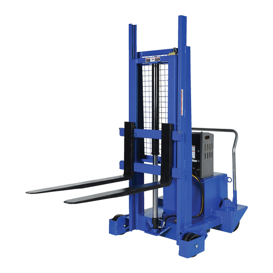
CB-PMPS Series Counterbalanced Pallet Handlers
Receiving Instructions:
After delivery, IMMEDIATELY remove the packaging from the product. Inspect the product closely to determine
whether it sustained damage during transport. If damage is discovered, immediately record a complete
description of the damage on the bill of lading. If the product is undamaged, discard the packaging.
NOTE:
Compliance with laws, regulations, codes, and non-voluntary standards enforced in the location where the product
is used is exclusively the responsibility of the end-user.
Table of Contents
Hazard identification with signal words.................................................................................................................... 2
Safe Use Recommendations.............................................................................................................................. 2
Product specifications by model........................................................................................................................... 3
Diagram of Hydraulic System.............................................................................................................................. 3
FIG. 1: CB-PMPS-6-50 exploded parts diagram & parts list............................................................................................. 4
FIG. 2: CB-PMPS-10-50 exploded parts diagram & parts list..................................................................................... 5
FIG. 3: CB-PMPS-6-60 exploded parts diagram & parts list....................................................................................... 6
FIG. 4: CB-PMPS-10-50 exploded parts diagram & parts list..................................................................................... 7
FIG. 5: 115VAC modular power unit electrical circuit diagram..................................................................................... 8
FIG. 6: 12VDC modular power unit electrical circuit diagram...................................................................................... 8
FIG. 7: Three phase AC modular power unit diagram............................................................................................... 9
FIG. 8: Single phase 208 / 230 VAC modular power unit diagram................................................................................. 9
FIGS. 9A & 9B: 12VDC modular power unit layout (parts 1 & 2).................................................................................. 10-11
FIG. 10: AC modular power unit layout.................................................................................................................. 12
FIGS. 11A & 11B: DC modular power unit exploded parts diagram............................................................................. 13-14
FIGS. 12A & 12B: AC modular power unit exploded parts diagram.............................................................................. 15-16
Loading Instructions.......................................................................................................................................... 17
Hydraulic system.............................................................................................................................................. 17-18
DC-Powered hydraulic system troubleshooting guide............................................................................................... 18-19
Battery charger operation................................................................................................................................... 20
Inspections & Maintenance............................................................................................................................................ 21-22
Labeling diagram.............................................................................................................................................. 22
Limited warranty............................................................................................................................................... 23
Copyright 2016 Vestil Manufacturing Corp.
V
M
ESTIL
ANUFACTURING
2999 North Wayne Street, P.O. Box 507, Angola, IN 46703
Telephone: (260) 665-7586 -or- Toll Free (800) 348-0868
Fax: (260) 665-1339
www.vestilmfg.com
Instruction Manual
CB-PMPS, manual.doc
C
.
ORP
e-mail:
sales@vestil.com
Page 1 of 23
Advertisement
Table of Contents

Subscribe to Our Youtube Channel
Summary of Contents for Vestil CB-PMPS Series
-
Page 1: Table Of Contents
Fax: (260) 665-1339 www.vestilmfg.com e-mail: sales@vestil.com CB-PMPS Series Counterbalanced Pallet Handlers Instruction Manual Receiving Instructions: After delivery, IMMEDIATELY remove the packaging from the product. Inspect the product closely to determine whether it sustained damage during transport. If damage is discovered, immediately record a complete description of the damage on the bill of lading. -
Page 2: Hazard Identification With Signal Words
Read the manual to refresh your understanding of proper use and maintenance procedures. DO NOT modify the product in any way UNLESS you first obtain written approval from Vestil. Unauthorized modifications might make the lift unsafe to use and automatically void the Limited Warranty (see p. 23). -
Page 3: Product Specifications By Model
83½ in. 3 in. to 60 in. 2,087 lb. CB-PMPS-10-60 ~455 kg 10 cm x 91 cm 231 cm 212 cm 7.6 cm x 152 cm 948.3 kg Diagram of Hydraulic System: Copyright 2016 Vestil Manufacturing Corp. Page 3 of 23... - Page 4 – 16 zinc-plated hex nut 37039 in. – 10 zinc-plated Nylock nut 16-001-190 Floor lock, model FL-ADJ-810 33012 in. USS zinc-plated flat washer 99-024-003 Guard,/Cover/End Cap/Plug 33625 in. lock washer 99-021-12 Telescoping cylinder, PMPS-50 Copyright 2016 Vestil Manufacturing Corp. Page 4 of 23...
- Page 5 Bolt, HHCS #2, zinc-plated, ”-10x3” 11 36209 in. – 13 plain hex jam nut 99-024-003 Guard, cover/endcap/plug in. – 13 x 1 in. HHCS #2 zinc-plated 12 11207 99-021-921 Telescopic cylinder, PMPS-50 bolt Copyright 2016 Vestil Manufacturing Corp. Page 5 of 23...
- Page 6 – 13 x 1 in. HHCS #2 zinc- 11 11207 99-024-003 Guard/cover/endcap/plug plated bolt 12 37030 in. – 13 Nylon insert lock nut 99-021-913 Telescopic cylinder, 58in. stroke Copyright 2016 Vestil Manufacturing Corp. Page 6 of 23...
- Page 7 – 13 x 1 in. HHCS #2 zinc- in.-10x3in. HHCS #2 zinc- 11 11207 11365 plated bolt plated bolt 12 37030 in. – 13 Nylon insert lock nut 99-021-913 Telescopic cylinder, 58in. stroke Copyright 2016 Vestil Manufacturing Corp. Page 7 of 23...
- Page 8 FIG. 5: 115VAC Modular power unit electrical circuit diagram Drawing no. 99-124-026, Rev. D Disconnect power before working on the FIG. 6: 12VDC Modular power unit electrical circuit diagram power unit! Drawing no. 99-124-026, Rev. D Copyright 2016 Vestil Manufacturing Corp. Page 8 of 23...
- Page 9 Disconnect power before working on the power unit! Drawing no. 99-124-032 FIG. 7: Single Phase 208/230VAC Modular Power Unit Diagram Disconnect power before working on the power unit! Drawing no. 99-124-033 Copyright 2016 Vestil Manufacturing Corp. Page 9 of 23...
-
Page 10: Figs. 9A & 9B: 12Vdc Modular Power Unit Layout (Parts 1 & 2)
11/1/2016 CB-PMPS, manual.doc Drawing no. 99133001 rev. A Copyright 2016 Vestil Manufacturing Corp. Page 10 of 23... - Page 11 11/1/2016 CB-PMPS, manual.doc Drawing no. 99133002 rev. A Copyright 2016 Vestil Manufacturing Corp. Page 11 of 23...
- Page 12 11/1/2016 CB-PMPS, manual.doc Drawing no. 99133003 rev. A Copyright 2016 Vestil Manufacturing Corp. Page 12 of 23...
-
Page 13: Figs. 11A & 11B: Dc Modular Power Unit Exploded Parts Diagram
11/1/2016 CB-PMPS, manual.doc FIG. 11A: DC Modular Power Unit Exploded Parts Diagram Copyright 2016 Vestil Manufacturing Corp. Page 13 of 23... - Page 14 11/1/2016 CB-PMPS, manual.doc FIG. 11B: DC Modular Power Unit Exploded Parts Diagram Copyright 2016 Vestil Manufacturing Corp. Page 14 of 23...
-
Page 15: Figs. 12A & 12B: Ac Modular Power Unit Exploded Parts Diagram
11/1/2016 CB-PMPS, manual.doc FIG. 12A: AC Modular Power Unit Exploded Parts Diagram Copyright 2016 Vestil Manufacturing Corp. Page 15 of 23... - Page 16 11/1/2016 CB-PMPS, manual.doc FIG. 12B: AC Modular Power Unit Exploded Parts Diagram Copyright 2016 Vestil Manufacturing Corp. Page 16 of 23...
-
Page 17: Loading Instructions
6.) Any modifications to the lift must be approved in writing by the manufacturer. HYDRAULIC SYSTEM Pushbutton controls are standard equipment on CB-PMPS series pallet handlers, i.e. a handheld controller as well as control buttons on the housing of the modular power unit. To raise or lower the fork carriage, press the appropriately marked button. -
Page 18: Dc-Powered Hydraulic System Troubleshooting Guide
Oil starvation causing pump to bind & See 2 (d), (f), (g), (h), (j) high internal heat develops. If this occurs, pump can be permanently damaged. r. Binding cylinders. Align cylinders correctly. Copyright 2016 Vestil Manufacturing Corp. Page 18 of 23... - Page 19 To unlock, re-pressurize the hydraulic present in the hydraulic system causing the system. velocity fuse to activate and shut off the oil flow from the cylinders. Consequently, deck will not lower. Copyright 2016 Vestil Manufacturing Corp. Page 19 of 23...
-
Page 20: Battery Charger Operation
3) Check the fuse. Replace only with a fuse having the same rating as originally supplied. 4) Determine battery condition. It may take some time before current begins to flow through a highly sulfated battery. Copyright 2016 Vestil Manufacturing Corp. Page 20 of 23... -
Page 21: Inspections & Maintenance
Step 2: Conduct a “Before each use”. If deformity, corrosion, rusting, or excessive wear of structural members is present, DO NOT use the pallet handler. Contact Vestil for instructions. If the carriage does not move smoothly or makes noise as it moves up or down the mast, apply a silicon wax or silicon spray to the inside of the mast frame. -
Page 22: Labeling Diagram
Numbers below label images in the diagram correspond to the identification number of each label. A: Label 220 B: Label 208 C: Label 295 D: Label 206 G: Label 527 E: Label 287 F: Label 212 Copyright 2016 Vestil Manufacturing Corp. Page 22 of 23... -
Page 23: Limited Warranty
(you) for warranty service. Who may request service? Only a warrantee may request service. You are a warrantee if you purchased the product from Vestil or from an authorized distributor AND Vestil has been fully paid.
Need help?
Do you have a question about the CB-PMPS Series and is the answer not in the manual?
Questions and answers