Advertisement
Quick Links
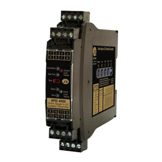
Strain Gauge/Bridge/Load Cell/Pressure Transducer to DC Transmitters, Field Rangeable
100 Ω to 10,000 Ω Bridges, 0.5 mV/V to 40 mV/V, 1-10 VDC Excitation
Input:
Output:
0-1 V to ±10 V or 0-2 mA to 4-20 mA (Sink or Source)
O Drive up to Four 350 Ω Bridges
O Adjustable Excitation Power Supply
O Sense Lead Compensation
O One Minute Setup for Hundreds of I/O Ranges
O Removable Plugs for Faster Installation
O Non-Interactive Zero and Span
O Full 3-Way Input/Output/Power Isolation
®
O Input and Output LoopTracker
LEDs
O Output Test or Calibration Resistor Options
Applications
Q Load Cell Weighing Systems and Scales
Q Strain Gauge Pressure Sensors and Transducers
Q Tanks, Scales, Extruder Melt Pressure, Crane Loads
Strain Gauge Input Ranges
100 Ω to 10,000 Ω bridges at 10 VDC
Up to four 350 Ω bridges at 10 VDC
Minimum:
0 to 5 mV range
0.5 mV/V sensitivity
Maximum:
0 to 400 mV range 40 mV/V sensitivity
Millivolt output range is determined by the sensor sensitivity
(mV/V) and the excitation voltage:
mV/V sensitivity X excitation voltage = total mV range
Input Impedance
200 kΩ typical
Common Mode Rejection
100 dB minimum
Calibration Resistor Options
M01 option: Switch with calibration resistor inside module.
Specify resistor value.
M02 option: Switch for external (load cell) calibration resistor.
Excitation Voltage
Switch Selectable: 0-10 VDC in 1 V increments
Maximum Output:
10 VDC maximum at 120 mA
Up to four 350 Ω bridges at 10 VDC
Drive Capability:
Fine Adjustment:
±5% via multi-turn potentiometer
Stability:
±0.01% per °C
Sense Lead Compensation
Better than ±0.01% per 1 Ω change in leadwire resistance
Maximum leadwire resistance: 10 Ω with 350 Ω at 10 VDC
LoopTracker
Variable brightness LEDs for input/output loop level and status
DC Output Ranges
Voltage (10 mA max.):
0-1 VDC
Bipolar Voltage (±10 mA max.): ±5 VDC
Current:
0-2 mADC to 0-20 mADC
20 V, 1000 Ω drive
Compliance, drive at 20 mA:
Current output can be selectively wired for sink or source
Output Calibration
Multi-turn zero and span potentiometers
±15% of span adjustment range typical
Zero offset switch: ±100% of span in 15% increments
Output Test
Sets output to test level when pressed
Adjustable 0-100% of span
Not available with M01 or M02 options
Output Ripple and Noise
Less than 10 mV
ripple and noise
RMS
Linearity
Better than ±0.1% of span
Ambient Temperature Range and Stability
–10°C to +60°C operating ambient
Better than ±0.02% of span per °C stability, nominal
Response Time
Nominal time at 63.2% of step change
Standard: 70 milliseconds (14.3 Hz)
DF option: Special response time, DF10 (10 milliseconds
or 100 Hz) up to DF5000 (5 seconds). Faster than standard
response times will cause output noise levels to be greater
than standard specifications. Contact factory for assistance.
Isolation
1200 V
min.
RMS
Full isolation: power to input, power to output, input to output
A
A
P
P
BSOLUTE
BSOLUTE
ROCESS
ROCESS
File E145968
85-265 VAC, 60-300 VDC
model only
Applications Link
api-usa.com/apps
Free Factory
I/O Setup!
1
Minute
Setup!
Housing and Connectors
IP 40, requires installation in panel or enclosure
For use in Pollution Degree 2 Environment
Mount vertically to a 35 mm DIN rail
Four 4-terminal removable connectors
14 AWG max wire size
Dimensions
0.89" W x 4.62" H x 4.81" D
22.5 mm W x 117 mm H x 122 mm D
Height includes connectors
Power
Standard:
85-265 VAC, 50/60 Hz or 60-300 VDC
D option:
9-30 VDC (either polarity) or 10-32 VAC
Power:
2 to 5 Watts depending on number of load cells
Description
to 0-10 VDC
The APD 4059 accepts an input from one to four strain gauges,
or ±10 VDC
bridge type sensors, load cells, or pressure transducers. It
filters, amplifies, and converts the resulting millivolt signal
into the selected DC voltage or current output that is linearly
related to the input.
The full 3-way (input, output, power) isolation makes this mod-
ule useful for ground loop elimination, common mode signal
rejection or noise pickup reduction.
The adjustable excitation power supply generates a stable
source of voltage to drive from one to four 350 Ω (or greater)
devices. Sense lead circuitry is included to cancel the effects
of leadwire resistance, if required.
Input, output, excitation and zero offset are field configurable,
via external rotary and slide switches. Offsets up to ±100%
of span can be used to cancel sensor offsets or non-zero
deadweights (taring). Non-interactive zero and span simplifies
calibration.
Model
APD 4059
APD 4059 D
Options—add to end of model number
M01
Switch with built-in calibration resistor.
Specify resistor value.
M02
Switch for external calibration resistor
DF
Special response time. Add DF to model number
followed by value in milliseconds (10 to 5000)
Option—add to end of model number
U
Conformal coating for moisture resistance
I
I
NSTRUMENTS
NSTRUMENTS
Connect mA Output
for Sink or Source
Hundreds of Range
Selections
Output LoopTracker
H H H H H H
H H H H H
H H H H H H
H H H H H
H H H H H H
LED
H H H H H
H H H H H H
H H H H H
H H H H H H
Test Switch for
Made in USA
Calibration Resistor
Zero and Span for
Output
Input LoopTracker
LED
Internal/External
Calibration Resistor
Options
Pb
Lead
Connect up to 4
Free
Load Cells
9 10 11 12
Input
Field configurable. Specify the following if
factory is to set switches
Bridge mV/V or mV range
Excitation voltage
1220 American Way Libertyville, IL 60048
Phone:
800-942-0315
Quick Link:
1 2 3 4
5 6 7 8
13 14 15 16
Universal Power
Sink/Source Versatility
For maximum versatility the APD 4059 milliamp output can be
selectively wired for sinking or sourcing. This allows connec-
tion to any type of mA input receiving device.
LoopTracker
API exclusive features include two LoopTracker LEDs (green for
input, red for output) that vary in intensity with changes in the
process input and output signals. These provide a quick visual
picture of your process loop at all times and can greatly aid in
saving time during initial startup and/or troubleshooting.
Output Test
An API exclusive feature includes the test button to provide a
fixed output (independent of the input) when held depressed.
The output test button greatly aids in saving time during initial
startup and/or troubleshooting. The test output level is potenti-
ometer adjustable from 0 to 100% of output span.
The output test is not available with the M01 or M02 options. A
calibration resistor switch replaces the test button.
Output
Field configurable. Specify follow-
85-265 VAC or 60-300 VDC
ing if factory is to set switches
Output range
Output type (V or mA)
Accessories—order as separately
SG-EQ4
Junction/sum board
SG-EQ4-BOXPG7 Junction/sum box
Trim pots for up to 4 strain gauges.
For 4-wire or 6-wire load cells.
API BP4 Spare 4 terminal plug, black
api-usa.com
Fax: 800-949-7502
APD 4059
api-usa.com/4059
Removable Plugs
See Wiring
Diagrams on
Page 3
Power
9-30 VDC or 10-32 VAC
© 05-20
Advertisement

Related Manuals for Absolute Process Instruments APD 4059 Series


Summary of Contents for Absolute Process Instruments APD 4059 Series
- Page 1 Strain Gauge/Bridge/Load Cell/Pressure Transducer to DC Transmitters, Field Rangeable APD 4059 100 Ω to 10,000 Ω Bridges, 0.5 mV/V to 40 mV/V, 1-10 VDC Excitation Input: Quick Link: api-usa.com/4059 Output: 0-1 V to ±10 V or 0-2 mA to 4-20 mA (Sink or Source) Connect mA Output O Drive up to Four 350 Ω...
- Page 2 Precautions, Range Setup APD 4059 Precautions Switch A Excitation Voltage range not corresponding nominally to 0 mV. Setting this WARNING! All wiring must be performed by a qualified electrician Refer to the sensor manufacturer's recommendations to deter- switch to “0” results in no offset. or instrumentation engineer.
- Page 3 Wiring, Installation, Calibration APD 4059 2 3 4 M01 Option: Internal Calibration Resistor Output Wiring Output 4-20 mA The APD 4059 M01 has a user-specified internal calibration Device resistor. A switch on the front of the module allows switching Current sinking output Cal.
- Page 4 Calibration, Operation, Diagnostics, Load Cell Information APD 4059 Calibration with Resistor Options M01 or M02 Output Test Function RED LoopTracker Output LED – Provides a visual indication Use this calibration procedure if your APD 4059 was ordered Models with the M01 or the M02 option do not have a Test that the output signal is functioning.