Table of Contents
Advertisement
Quick Links
Strain Gauge/Bridge/Load Cell/Pressure Transducer to DC Transmitters, Field Rangeable
100 Ω to 10,000 Ω Bridge, 0.5 mV/V to 120 mV/V, 1-10 VDC Excitation
0-1 V to ±10 V or 0-2 mA to 4-20 mA (Sink or Source), Non-Isolated
O Adjustable Excitation Power Supply
O One Minute Setup for Hundreds of I/O Ranges
O Removable Plugs for Faster Installation
®
O Input and Output LoopTracker
LEDs
O Output Test or Calibration Resistor Options
Applications
Q Load Cell Weighing Systems and Scales
Q Strain Gauge Pressure Sensors and Transducers
Q Tanks, Scales, Extruder Melt Pressure, Crane Loads
Strain Gauge Input Ranges
Minimum range:
0 to 5 mV
Maximum range:
0 to 1200 mV
Minimum sensitivity:
0.5 mV/V
Maximum sensitivity: 120 mV/V
Millivolt output range is determined by the sensitivity of the
sensor (mV/V) and the excitation voltage applied.
mV/V sensitivity X excitation voltage = total mV range
Input Impedance
1 MΩ typical
Common Mode Rejection
100 dB minimum
Calibration Resistor Options
M01 option: Switch with calibration resistor inside module.
Specify resistor value.
M02 option: Switch for external (load cell) calibration resistor.
Excitation Voltage
Maximum output: 10 VDC maximum at 30 mA
One 100 Ω to 10,000 Ω bridge at 10 VDC
Drive capability:
Switch selectable: 0-10 VDC in 1 V increments
Fine adjustment: ±2.5% via multiturn potentiometer
Stability:
±0.01% per °C
LoopTracker
Variable brightness LEDs for input/output loop level and status
DC Output Ranges
Minimum
Maximum
Voltage:
0-1 VDC
0-10 VDC (10 mA max)
Bipolar Voltage:
±1 VDC
±10 VDC (±10 mA max)
Current:
0-2 mADC
4-20 mADC
20 V compliance, 1000 Ω at 20 mA
Output Calibration
Multi-turn zero and span potentiometers
±15% of span adjustment range typical
Zero offset switch: ±100% of span in 15% increments
Output Test
Sets output to test level when pressed
Potentiometer adjustable 0-100% of span
Not available with M01 or M02 options
Output Ripple and Noise
Less than 10 mV
ripple and noise
RMS
Linearity
Better than ±0.1% of span
Ambient Temperature Range and Stability
–10°C to +60°C operating ambient
Better than ±0.02% of span per °C stability
Response Time
Nominal time at 63.2% of step change
Standard: 70 milliseconds (14.3 Hz)
DF10 option: Fast response time, 10 milliseconds (100 Hz)
nominal. DF option will cause output noise levels to be
greater than standard specifications. See APD 4059 for custom
response times.
Housing and Connectors
IP 40, requires installation in panel or enclosure
For use in Pollution Degree 2 Environment
Mount vertically to a 35 mm DIN rail
Four 4-terminal removable connectors, 14 AWG max wire size
Power
Standard:
85-265 VAC, 50/60 Hz or 60-300 VDC
D option:
9-30 VDC (either polarity) or 10-32 VAC
Power:
2 to 5 Watts depending on number of load cells
A
A
P
P
BSOLUTE
BSOLUTE
ROCESS
ROCESS
File E145968
85-265 VAC, 60-300 VDC
model only
H H H H H H
H H H H H
H H H H H H
H H H H H
H H H H H H
H H H H H
H H H H H H
H H H H H
H H H H H H
Made in USA
Applications Link
api-usa.com/apps
Free Factory
I/O Setup!
1
Minute
Setup!
Connect One 100 Ω to
10,000 Ω Load Cell
Pb
Lead
Free
Dimensions
0.89" W x 4.62" H x 4.81" D
22.5 mm W x 117 mm H x 122 mm D
Height includes connectors
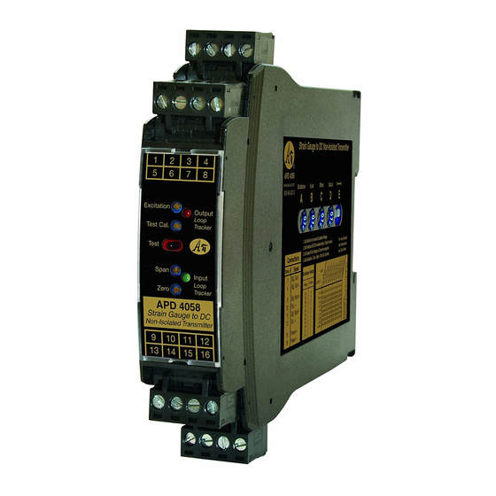
Description
The APD 4058 accepts an input from a strain gauge, bridge
type sensor, load cell, or pressure transducer.
It filters, amplifies, and converts the resulting millivolt signal
into the selected DC voltage or current output that is linearly
related to the input. The output is not electrically isolated.
The adjustable excitation power supply generates a stable
source of voltage to drive your sensor.
Input, output, excitation and zero offset are field configurable,
via external rotary and slide switches.
Offsets up to ±100% of span can be used to cancel sensor
offsets or non-zero deadweights (taring).
Sink/Source Versatility
For maximum versatility the APD 4058 milliamp output can be
selectively wired for sinking or sourcing. This allows connec-
tion to any type of mA input receiving device.
Model
Field configurable. Specify the following if
APD 4058
factory is to set switches
Bridge mV/V or mV range
APD 4058 D
Excitation voltage
Options—add to end of model number
M01
Switch with built-in calibration resistor. Specify
resistor value.
M02
Switch for external calibration resistor.
R
Input/output reversal, such as 20-4 mA output
DF10
10 millisecond response time.
I
I
NSTRUMENTS
NSTRUMENTS
Connect mA Output
1 2 3 4
for Sink or Source
Hundreds of Range
Selections
5 6 7 8
Output LoopTracker
LED
Adjustable Output
Test Function
Zero and Span for
Output
Input LoopTracker
LED
External or Internal
Calibration Resistor
Options
9 10 11 12
Universal
13 14 15 16
Power
LoopTracker
API exclusive features include two LoopTracker LEDs (green for
input, red for output) that vary in intensity with changes in the
process input and output signals. These provide a quick visual
picture of your process loop at all times and can greatly aid in
saving time during initial startup and/or troubleshooting.
Output Test
An API exclusive feature includes the test button to provide a
fixed output (independent of the input) when held depressed.
The output test button greatly aids in saving time during initial
startup and/or troubleshooting. The test output level is potenti-
ometer adjustable from 0 to 100% of output span.
The output test is not available with the M01 or M02 options. A
calibration resistor switch replaces the test button.
Input
Field configurable. Specify follow-
ing if factory is to set switches
Output range
Output type (V or mA)
Option—add to end of model number
U
Accessory—order as separate line item
API BP4 Spare removable 4 terminal plug, black
1220 American Way Libertyville, IL 60048
Phone:
800-942-0315
Fax: 800-949-7502
APD 4058
Quick Link:
api-usa.com/4058
Removable Plugs
See Wiring
Diagrams on
Output
Power
85-265 VAC or 60-300 VDC
9-30 VDC or 10-32 VAC
Conformal coating for moisture resistance
api-usa.com
Page 3
© 11-19
Advertisement
Table of Contents

Related Manuals for Absolute Process Instruments APD 4058 Series


Summary of Contents for Absolute Process Instruments APD 4058 Series
- Page 1 Strain Gauge/Bridge/Load Cell/Pressure Transducer to DC Transmitters, Field Rangeable APD 4058 100 Ω to 10,000 Ω Bridge, 0.5 mV/V to 120 mV/V, 1-10 VDC Excitation Input: Quick Link: api-usa.com/4058 Output: 0-1 V to ±10 V or 0-2 mA to 4-20 mA (Sink or Source), Non-Isolated O Adjustable Excitation Power Supply Connect mA Output O One Minute Setup for Hundreds of I/O Ranges...
- Page 2 Precautions, Range Setup APD 4058 Precautions Range Selection Offset Switch C WARNING! All wiring must be performed by a qualified electrician Offset switch C allows canceling or taring of non-zero Switch A: Excitation voltage or instrumentation engineer. See diagram for terminal designa- deadweights or other sensor offsets such as: Switch B: Input range...
- Page 3 Wiring and Installation APD 4058 Settings for Push-Pull Load Cells Mounting to a DIN Rail Output Wiring 4-20 mA The input range can be thought of as a percentage scale. Install module vertically on a 35 mm DIN rail in a protective Device Zero percent of the signal range will be a negative number for enclosure away from heat sources.
- Page 4 Calibration, Operation, Diagnostics, Load Cell Information APD 4058 Basic Calibration Output Test Function Operation he Zero, Span, and Excitation potentiometers are used to cali- Models with the M01 or the M02 option do not have a Test Strain gauges and load cells are normally passive devices brate the output.
Need help?
Do you have a question about the APD 4058 Series and is the answer not in the manual?
Questions and answers