Table of Contents
Troubleshooting

Summary of Contents for General Photonics PDLE-101
- Page 1 PDLE–101 PDL Emulator Operation Manual Version 1.1 June 6, 2011 General Photonics Corp. Ph: (909) 590-5473 5228 Edison Ave. Fax: (909) 902-5536 Chino, CA 91710 USA www.generalphotonics.com Document #: GP-UM-PDLE-101-11 Page 1 of 61...
-
Page 2: Warranty
WARRANTY All of General Photonics’ products have been inspected and found to comply with our stringent quality assurance standards before shipping. If any damage occurs during shipment, please contact the carrier and inform us or our distributors as soon as possible. - Page 3 Failure to comply with these precautions or with specific warnings elsewhere in this manual violates safety standards of design, manufacture, and intended use of the instrument. General Photonics Corp. assumes no liability for customers’ failure to comply with these requirements.
-
Page 4: Table Of Contents
4.4.2.1 Procedure for Installing USB VCP driver ..........30 4.4.2.2. VCP Uninstall Procedure:................ 39 4.4.2.4. USB Troubleshooting: ................40 4.4.3. PDLE-101 GPIB and Ethernet Control............. 41 4.4.4. Remote Control Program Interface............50 Section 5. Technical Support .................... 61 Document #: GP-UM-PDLE-101-11... -
Page 5: Section 1. Specifications
RS-232, USB, Ethernet, GPIB Trigger Signal 5V TTL signal, 5mA min. Minimum pulse width 150ns Notes: 1. Other wavelength ranges available upon request. 2. At 23±5°C. 3. Rise time for square wave transition. Document #: GP-UM-PDLE-101-11 Page 5 of 61... -
Page 6: Section 2. Overview
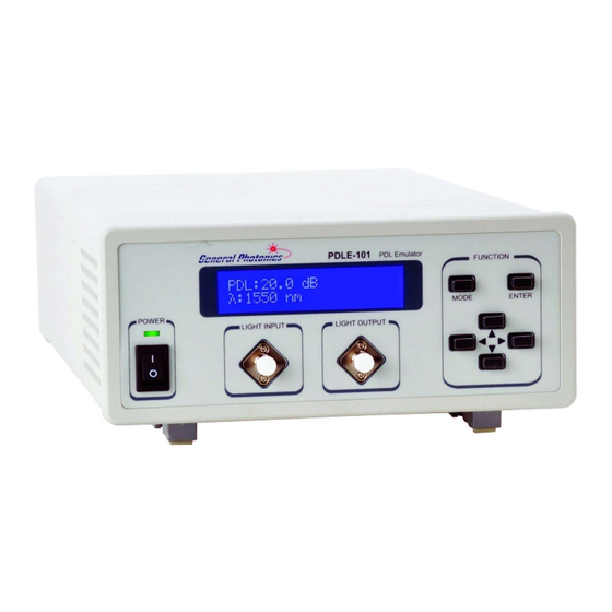
40Gb/s and 100Gb/s data transmission, must therefore meet stringent PDL tolerance specifications. General Photonics’ PDLE-101 is a PDL emulator specifically designed for PDL tolerance testing of high speed telecommunication systems. It is available with wavelength calibrations for either the C or L bands, and can generate discrete PDL values up to 20 dB with a resolution of 0.1 dB in less than 5 ms. - Page 7 Figure 2 PDL Emulator. The PDLE-101 employs a large character, backlit liquid crystal display (LCD) for easy readout. In addition to front panel control, it can be remote controlled via built-in RS-232, USB, Ethernet, or GPIB interfaces. Document #: GP-UM-PDLE-101-11...
-
Page 8: Section 3. Feature Description
Although the PDLE is shipped with a standard FC fiber adapter, other interchangeable inserts are available. For additional information on different input fiber adapter inserts, please contact General Photonics. External fiber connectors should be cleaned using industry standard cleaning methods before connection to the PDLE. -
Page 9: Electrical Features
• The PDLE-101 is not user serviceable and can be serviced only by factory- authorized personnel. The front panel of the PDLE-101 is shown in Figure 4. The power switch (Power), liquid crystal display (LCD), push button control pad, and optical connectors are mounted on the front panel. - Page 10 Rear panel description: USB: USB interface port RS-232: serial communication port Ethernet: Ethernet interface port BNC: trigger signal input Line: external AC supply input connector, 100-240 V GPIB: GPIB interface port : chassis ground connector Document #: GP-UM-PDLE-101-11 Page 10 of 61...
- Page 11 15,000 V/ μs =1000Volts, and can be triggered with a minimum current of 5mA. Trigger pulses must be +5 Volts LSTTL/TTL compatible, with a minimum pulse width of 150 ns. Document #: GP-UM-PDLE-101-11 Page 11 of 61...
-
Page 12: Section 4. Operation Instructions
Main Display Screen The main display screen shows the current PDL and wavelength settings. 4. Connect the input and output fibers to the PDLE-101. It is important to clean the fiber connectors using industry standard procedures before connecting them. In the case of a high power laser source, turn off the optical power source before connector cleaning. - Page 13 1. PDL TRI VARIATION 2. PDL RAN VARIATION ↓ 3. PDL SIN VARIATION ↑ 4. PDL SQU VARIATION Document #: GP-UM-PDLE-101-11 Page 13 of 61...
- Page 14 PDL TRIANGLE WAVE VARIATION: This is a constant-rate sweep function using a triangular waveform. The PDLE-101 sweeps the PDL back and forth between the selected minimum and maximum values at the selected frequency. Figure 7 PDL triangular sweep function When the function is first called, the instrument will be in parameter setting mode. The sweep function is disabled.
- Page 15 4.6 ms after the new trigger edge. 4.6 ms variation trigger To return to the main screen, press the MODE button 3 times. Document #: GP-UM-PDLE-101-11 Page 15 of 61...
- Page 16 PDL RANDOM VARIATION: In this function, the PDLE-101 generates random PDL values within the range defined by the selected minimum and maximum values. The dwell time at each value is determined by the frequency selection. For example, if the frequency is 1 Hz, the instrument will hold each value for 1 second before switching to the next.
- Page 17 To return to the main screen, press the MODE button 3 times. PDL SINE WAVE VARIATION: This is a sinusoidal sweep function. The PDLE-101 sweeps the PDL back and forth between the selected minimum and maximum values at the selected frequency.
- Page 18 The sine wave variation will begin 4.6ms after the trigger edge. If a second trigger pulse is received after the sine variation has begun, it will reset and restart 4.6 ms after the new trigger edge. Document #: GP-UM-PDLE-101-11 Page 18 of 61...
- Page 19 To return to the main screen, press the MODE button 3 times. PDL SQUARE WAVE VARIATION: In this function, the PDLE-101 switches the PDL back and forth between the selected minimum and maximum points, executing a square wave at the selected frequency.
- Page 20 Subsequently, it will toggle between states once for each trigger pulse. The delay between the trigger edge and the PDL transition is 420µs. The timing diagram is shown below, for triggered operation on the rising edge. Document #: GP-UM-PDLE-101-11 Page 20 of 61...
- Page 21 420µs after the new trigger edge. The timing diagram is shown below. 420µs variation trigger To return to the main screen, press the MODE button 3 times. Document #: GP-UM-PDLE-101-11 Page 21 of 61...
- Page 22 Rise and Fall (for Edge selection). The selections are applied immediately; it is not necessary to press ENTER after making a selection. From this screen, press the MODE button twice to return to the main screen. Document #: GP-UM-PDLE-101-11 Page 22 of 61...
- Page 23 If no static IP address has been stored by the user, the address displayed will be 0.0.0.0. Get Static IP: Sets the instrument for static IP addressing and recalls the static IP address stored in memory. Document #: GP-UM-PDLE-101-11 Page 23 of 61...
- Page 24 Use the left and right arrow keys to move between digits and the up and down arrow keys to increment the highlighted digit. Press the ENTER key to move the cursor back to parameter selection (cursor blinking on the option letter). Document #: GP-UM-PDLE-101-11 Page 24 of 61...
- Page 25 Use the arrow keys to select the desired address, then press ENTER to update and store the new address to memory. The GPIB address range is 1 to 30. From this screen, press the MODE button twice to return to the main screen. Document #: GP-UM-PDLE-101-11 Page 25 of 61...
-
Page 26: Remote Control And Programming
(See the PDLE-101 command list in the next section). The RS-232 connector on the rear panel of the PDLE-101 is a DB9 male connector. Use a straight connection RS-232 cable to connect the PDLE-101 to the RS-232 port of a computer. - Page 27 Note: These commands are common to all communication interfaces. System Command Description Response *IDN? Queries the product number *GP PDLE-101 V1.1# *VER? Queries the Firmware Version *V1.0.100524A-G# (Sample response) *SER? Queries instrument serial number Example: * 136000000007# Set GPIB Address nn...
- Page 28 Range: 0.2 dB ≤ Max ≤ 20.0 dB Queries PDL Random Variation Maximum PDL Response: *FF.f# *RAN MXA? Units: dB Example: *15.0# Max PDL set to 15.0 dB Range: 0.2 dB ≤ Max ≤ 20.0 dB Document #: GP-UM-PDLE-101-11 Page 28 of 61...
- Page 29 Note: Min PDL must be less than Max PDL Queries PDL Square Wave Minimum PDL Response: *FF.f# *SQU MNA? Units: dB Example: *2.5# Min PDL set to 2.5 dB Range: 0.1 dB ≤ Min ≤ 19.9 dB Document #: GP-UM-PDLE-101-11 Page 29 of 61...
-
Page 30: Rs-232 Troubleshooting
9600 bps. 2. Only one command is allowed in each command string. 3. The PDLE-101 should respond to control commands with one of the error codes listed above. If a command is a status request, the computer will return either the requested information or an error code of form *Enn#;... - Page 31 3. Click “Next”: 4. Click “Next”: Document #: GP-UM-PDLE-101-11 Page 31 of 61...
- Page 32 5. Check “Specify a location”, then click “Next”: Document #: GP-UM-PDLE-101-11 Page 32 of 61...
- Page 33 6. Use “Browse” to locate the file directory where the VCP driver is. Click “OK” to proceed to the next screen: 7. Click “Next”: Document #: GP-UM-PDLE-101-11 Page 33 of 61...
- Page 34 8. Click “Finish”. This completes the first part of the installation, during which the USB to serial converter is installed. The second part consists of the installation of the serial port driver. This should follow automatically once the converter installation is completed: 9. Click “Next”: Document #: GP-UM-PDLE-101-11 Page 34 of 61...
- Page 35 10. Click “Next”: 11. Use “Browse” to locate the file directory where the VCP driver is. Click “OK” to proceed to the next screen: Document #: GP-UM-PDLE-101-11 Page 35 of 61...
- Page 36 12. Click “Next”: 13. Click “Finish”. Document #: GP-UM-PDLE-101-11 Page 36 of 61...
- Page 37 The device should have installed as a USB Serial Port (COMx) attached to USB High Speed Serial Converter. The USB driver can drive more than one instrument, but the correct port number must be set in the control programs for each of the instruments. Document #: GP-UM-PDLE-101-11 Page 37 of 61...
- Page 38 In this example, the USB device is connected to COM3. Document #: GP-UM-PDLE-101-11 Page 38 of 61...
-
Page 39: Vcp Uninstall Procedure
4.4.2.2. VCP Uninstall Procedure: Unplug device. Run “Add/Remove Programs” from Control Panel: Document #: GP-UM-PDLE-101-11 Page 39 of 61... -
Page 40: Usb Troubleshooting
4.4.2.3. PDLE-101 USB Commands The command list for USB control is the same as for RS-232 (see Table 1 and the accompanying notes in section 4.4.1.2.) 4.4.2.4. USB Troubleshooting: Sometimes, for unknown reasons, the USB Serial Port cannot be found in Device Manager. -
Page 41: Pdle-101 Gpib And Ethernet Control
4.4.1.2.) GPIB: While controlled by the IEEE 488 GPIB interface, the PDLE-101 can function as a Talker or Listener on a bus with up to 14 other GPIB devices. The PDLE-101 uses the CB7210.2 GPIB chip. Ethernet:... - Page 42 Figure 12. For this configuration, a standard straight-linked network cable must be used. PDLE-101 PDLE-101 Figure 11 Direct connection: PDLE-101 to PC Figure 12 Connect PDLE-101 with DHCP server 2. Set Ethernet configuration and get IP address: a) Front panel: As described in section 4.2, the user can set the PDLE for static or dynamic IP...
- Page 43 The program has 3 tabs. The first, “GET IP CONFIG” is used to query the current IP configuration of the PDLE-101. When the “Get IP Config” button at the left of the screen is clicked, the program will read back the instrument’s current IP address, net mask, gateway, nameserver, and port, as well as whether the instrument is currently set for static or dynamic IP addressing.
- Page 44 IP Config query screen- Dynamic IP mode result Use this function to obtain the IP address, which is needed to control the PDLE-101 via Ethernet. The second tab, “MODE SETTING” allows the user to switch the PDLE-101 between static and dynamic IP addressing modes.
- Page 45 IP configuration information can be used for communication. If the PDLE-101 is powered off while in dynamic IP mode, when it is powered back on, it will be in dynamic IP mode.
- Page 46 254. In this example, n = 0, so the available IP addresses are 1 to 254. If the computer’s IP address is 17, for example, the user can set the IP address for the PDLE-101 to any number in the range 1-254 except 17.
- Page 47 → Properties (on “General” tab) → Internet Protocol → Properties: Document #: GP-UM-PDLE-101-11 Page 47 of 61...
- Page 48 To use dynamic IP address assignment, make sure that the DHCP server, switch, computer and PDLE-101 are correctly connected as shown in Figure 12. Check that the correct cables are used and that everything is powered on. Also, check that the control computer is set to obtain its IP address automatically.
- Page 49 → Properties (on “General” tab) Document #: GP-UM-PDLE-101-11 Page 49 of 61...
-
Page 50: Remote Control Program Interface
4.4.4. Remote Control Program Interface LabView based control programs are provided for computer control of the PDLE-101 through different control interfaces. If the LabView development environment (version 8.2 or above) is installed on the control computer, either the source code (vi) or the executable versions of the remote control programs can be used without installing further drivers. - Page 51 Connection” button at the top left of the screen. The program will attempt to connect to the PDLE. If the connection is successful, the connection status indicator at the top left of the screen will turn green, and the main screen will show the single PDL setting interface. Document #: GP-UM-PDLE-101-11 Page 51 of 61...
- Page 52 To use an interface other than Ethernet, make sure that the necessary hardware connections are in place, then click the RS232/USB/GPIB button on the initial interface query window. The program will initiate a port search: Document #: GP-UM-PDLE-101-11 Page 52 of 61...
- Page 53 Port selection menu Connection status Communication indicator interface indicator/ selection button If the connection is successful, the connection status indicator will turn green and the main screen will show the single PDL setting interface. Document #: GP-UM-PDLE-101-11 Page 53 of 61...
- Page 54 ENTER or click outside the text box whose value has just been changed. Ranges: PDL: 0.1 to 20 dB Wavelength: 1520 to 1570nm Document #: GP-UM-PDLE-101-11 Page 54 of 61...
- Page 55 Enable/Disable Click the “Triangle Enable/Disable” button to enter triangle mode. The interface screen is displayed above. The indicator boxes in the middle of the screen display the waveform/trigger status, frequency, and scan limits. Document #: GP-UM-PDLE-101-11 Page 55 of 61...
- Page 56 Each subsequent pulse will restart the triangle variation. Sine Waveform This mode generates a sine wave variation with user-set endpoints and frequency. Document #: GP-UM-PDLE-101-11 Page 56 of 61...
- Page 57 This mode generates a series of random values bounded by the user-set endpoints. If triggered operation is on, a random point is generated for each trigger pulse. If triggered operation is off, random states are generated at the user-set frequency (e.g. 1 Hz = 1 point/sec.) Document #: GP-UM-PDLE-101-11 Page 57 of 61...
- Page 58 ENTER or click outside the box whose value has just been modified. Ranges: Frequency: 0.1 to 100 Hz Max. PDL: 0.2 to 20 dB Min. PDL: 0.1 to 19.9 dB Document #: GP-UM-PDLE-101-11 Page 58 of 61...
- Page 59 Click the “Square Enable/Disable” button to enter square wave mode. The interface screen is displayed above. The indicator boxes in the middle of the screen display the waveform/trigger status, frequency, and scan limits. Document #: GP-UM-PDLE-101-11 Page 59 of 61...
- Page 60 If the trigger is on and the frequency is set to 0.0 Hz, the PDLE will switch once between states each time it receives a trigger pulse. The first transition will be from low to high PDL. Subsequently, it will toggle between states once for each trigger pulse. Document #: GP-UM-PDLE-101-11 Page 60 of 61...
-
Page 61: Section 5. Technical Support
Section 5. Technical Support General Photonics is committed to high quality standards and customer satisfaction. For any questions regarding the quality and use of the PDLE-101, or future suggestions, please contact General Photonics Corporation at (909)-590-5473 (telephone) or (909)- 902-5536 (fax), or by e-mail at info@generalphotonics.com. General Photonics will respond to all customer questions within 24 hours during regular business hours.
Need help?
Do you have a question about the PDLE-101 and is the answer not in the manual?
Questions and answers