Table of Contents
Advertisement
Quick Links
Advertisement
Table of Contents

Summary of Contents for Ascor Giga-tronics 3000-43
- Page 1 Artisan Technology Group is your source for quality new and certified-used/pre-owned equipment SERVICE CENTER REPAIRS WE BUY USED EQUIPMENT • FAST SHIPPING AND DELIVERY Experienced engineers and technicians on staff Sell your excess, underutilized, and idle used equipment at our full-service, in-house repair center We also offer credit for buy-backs and trade-ins •...
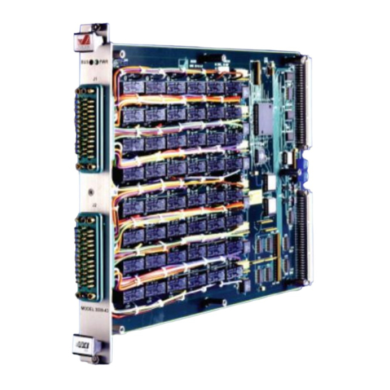
- Page 2 Manual 07500860 Model 3000-43 Model 3000-43 48 SPST Relays 90400830 Page 1 peration Manual Artisan Technology Group - Quality Instrumentation ... Guaranteed | (888) 88-SOURCE | www.artisantg.com...
- Page 3 Manual 07500860 Model 3000-43 All technical data and specifications in this publication are subject to change without prior notice and do not represent a commitment on the part of Giga-tronics, Incorporated. © 2011 Giga-tronics Incorporated. All rights reserved. Printed in the U.S.A. Warranty 3000 Switching Modules Giga-tronics Series...
- Page 4 Manual 07500860 Model 3000-43 Regulatory compliance information This product complies with the essential requirements of the following applicable European Directives, and carries the CE mark accordingly. 89/336/EEC and 73/23/EEC EMC Directive and Low Voltage Directive EN61010-1 (1993) Electrical Safety EN61326-1 (1997) EMC –...
- Page 5 Manual 07500860 Model 3000-43 Record of Changes to This Manual Use the table below to maintain a permanent record of changes to this document. Corrected replacement pages are issued as Technical Publication Change Instructions (TPCI). When you are issued a TPCI, do the following: 1.
- Page 6 Manual 07500860 Model 3000-43 Revision History Revision Description of Change Chg Order # Approved By Initial Release Updated Reformatted 3/12 Page 5 peration Manual Artisan Technology Group - Quality Instrumentation ... Guaranteed | (888) 88-SOURCE | www.artisantg.com...
-
Page 7: Table Of Contents
8.2 Switch Matrix Register Map ......................16 8.3 Connector Configuration ........................19 Chapter 9 Programming ..........................20 9.1 Introduction ............................20 9.2 ASCOR 3000-43 Module Overview ....................20 9.2.1 VXI Register Based Modules ...................... 20 Page 6 peration Manual Artisan Technology Group - Quality Instrumentation ... Guaranteed | (888) 88-SOURCE | www.artisantg.com... - Page 8 9.2.8 VXI Device Class Dependent Registers ..................28 9.2.9 VXI Device Dependent Registers for the 3000-43 ..............28 9.3 ASCOR Custom Registers for the ASCOR 3000-43 Module .............. 31 9.3.1 ASCOR Relay Registers ......................32 9.4 Programming VXI Device Registers....................32 9.4.1 Resetting ASCOR VXI Module ....................
-
Page 9: Chapter 1 Introduction
Manual 07500860 Model 3000-43 Chapter 1 Introduction 1.1 Safety and Manual Conventions This manual contains conventions regarding safety and equipment usage as described below. 1.1.1 Product Reference Throughout this manual, the term “Common Core Switching Platform, Series 8800” refers to all models of within the series, unless otherwise specified. -
Page 10: Chapter 2 Configuration Table
Manual 07500860 Model 3000-43 Chapter 2 Configuration Table Module PL90400830 Assy 90400830 Schematics PL85002340 Assy 85002340 SCH85002340 Page 9 peration Manual Artisan Technology Group - Quality Instrumentation ... Guaranteed | (888) 88-SOURCE | www.artisantg.com... -
Page 11: Chapter 3 Functional Description
All 48 relays are controlled via three 16-bit program registers. The registers are accessed by the controller in high speed data transfer using 16 bit or 32 bit data format using ASCOR’s VXImax™ technology. The state of each relay can be read by the VXI controller. -
Page 12: Chapter 4 Block Diagram
Manual 07500860 Model 3000-43 Chapter 4 Block Diagram 48 Channels Analog Groundplane Page 11 peration Manual Artisan Technology Group - Quality Instrumentation ... Guaranteed | (888) 88-SOURCE | www.artisantg.com... -
Page 13: Chapter 5 Controls And Indicators
Manual 07500860 Model 3000-43 Chapter 5 Controls and Indicators The following controls and indicators are provided to select and display the functions of the ASCOR 3000-43 Module’s operating environment. 5.1 VXI Logical Address The Logical Address Switch is dual circular switches, D1 and D2 which are located at the rear of the module. -
Page 14: Chapter 6 Internal Settings
The following items are inside the module and can be reached by removing the side cover. 6.1 Fuse The ASCOR VXI 3000-43 uses a 10 Amp fuse in the +5 Volt line and is located on the Mother Board (MB) assembly. -
Page 15: Chapter 7 Specifications
Manual 07500860 Model 3000-43 Chapter 7 Specifications SPST relays: Electrical: Max. Switching Voltage (DC/Peak AC, Resistive) 150 DC, 250 VAC Max. Switching Current (DC/Peak AC, Resistive) 10 Amps Max. Power Rating (DC/Peak AC, Resistive) 300 Watts or 2000VA Life Expectancy (@ Signal <<1.0V, 0.010A) 10,000,000 Contact resistance: <<... -
Page 16: Chapter 8 Register Map
A24 Base Address. All other bits in the A24 Base Address are set to zeroes. A subset of the ASCOR 3000-43 Custom Registers are relay registers. See connector assignments for pin and channels assignments with associated relays. -
Page 17: Switch Matrix Register Map
Manual 07500860 Model 3000-43 8.2 Switch Matrix Register Map The following diagram shows the signal name and register assignments for the switch matrices. DESCRIPTION: 48 SPST RELAYS PCB NUMBER: 85002340 @MINORHEADING = MODE: MODE: 15(3 14(3 13(2 12(2 11(27 10(2 8000h- 8000h lower... - Page 18 Manual 07500860 Model 3000-43 Switch Matrix Register Map (Continued) REGISTER: 8000h, MODE: 16/32 bit FUNCTION: Relays K1-16 CONNECTION RELAY no:J1-A, c:J1-B no:J1-C, c:J1-D no:J1-E, c:J1-F no:J1-H, c:J1-J no:J1-K, c:J1-L no:J1-M, c:J1-N no:J1-P, c:J1-R no:J1-S, c:J1-T no:J1-U, c:J1-V no:J1-W, c:J1-X no:J1-Y, c:J1-Z no:J1-a, c:J1-b no:J1-c, c:J1-d no:J1-e, c:J1-f...
- Page 19 Manual 07500860 Model 3000-43 REGISTER: 8000h, MODE: 32 bit@ BITS 16-31 REGISTER: 8004h, MODE: 16 bit FUNCTION: K33-48 CONNECTION RELAY 0 (16) no: J2-U@ c: J2-V 1 (17) no: J2-W@ c: J2-X 2 (18) no: J2-Y@ c: J2-Z 3 (19) no: J2-a@ c: J2-b 4 (20) no: J2-c@ c: J2-d...
-
Page 20: Connector Configuration
Manual 07500860 Model 3000-43 8.3 Connector Configuration CONNECTOR - J1 CONNECTOR - J2 CONN. TO CONN. RELAY CONN. TO CONN. RELAY J1-A TO J1-B J2-A TO J2-B J1-C TO J1-D J2-C TO J2-D J1-E TO J1-F J2-E TO J2-F J1-H TO J1-J J2-H TO J2-J... -
Page 21: Chapter 9 Programming
A16 address space are VXI Device Registers. They are accessed as a 16-bit word. The registers located in the A24 address space are ASCOR Module Custom registers, and they can be accessed as a 16-bit word. Additionally, since the 3000-43 is equipped with VXIMAXTM 16/32, these Custom registers can also be accessed as a 32-bit word. -
Page 22: Vxi Device Register Description
9.2.6 VXI Device Register Description The ASCOR 3000-43 General Purpose Switch has VXI Device Registers located in the A16 address space. The VXI Specification defines 32 VXI Device Registers and they are all 16 bits wide. The first 4 registers are VXI Configuration Registers. - Page 23 Manual 07500860 Model 3000-43 Page 22 peration Manual Artisan Technology Group - Quality Instrumentation ... Guaranteed | (888) 88-SOURCE | www.artisantg.com...
-
Page 24: Vxi Configuration Registers
Device Class: This field indicates the classification of the VXIbus device. 00b = Memory 01b = Extended 10b = Message Based xxx = Register Based (ASCOR VXI Module) (Bits 13-12) Address Space: This field indicates the addressing mode(s) of the device’s operational registers. 00b = A16/A24... - Page 25 Model Code: This field contains the manufacturer’s unique module identifier. F2Bh = The ASCOR Model Code for the 3000-43. This number is different from the ASCOR Model number. For the 3000-43 Module, the register should read back a value of 7F2Bh.
- Page 26 Manual 07500860 Model 3000-43 Offset Description Status Register (read) / Control Register (write) A read of this 16-bit register provides information about the 3000-43 status. 12 11 10 A24/A32 MODID Device Rea- Pas- Dev. Dependent Dep. (Not used) (Bit 15) A24/A32 Active: This bit indicates the accessibility of A24 or A32 registers.
- Page 27 Manual 07500860 Model 3000-43 A write to this 16-bit register causes specific actions to be executed. A24/A32 Device Dependent Sys- Dev.Rst (Not used) fail (Bit 15) A24/A32 Enable: This bit enables or disables A24 / A32 VMEbus registers. 1b = Enables A24 or A32 VMEbus registers.
- Page 28 Manual 07500860 Model 3000-43 Offset Register (read/write) A read of the 16-bit register provides information for calculating the base address of the 3000- 43 A24 operational registers. Offset Value used (Bits 15-8) Offset Value: This field is used for calculating the A24 Base Address. (Bits 7-0) Don’t Care bits (Not used) To obtain the A24 base address for the 3000-43, take the 8 most significant bits...
-
Page 29: Vxi Device Class Dependent Registers
Manual 07500860 Model 3000-43 9.2.8 VXI Device Class Dependent Registers The ASCOR 3000-43 General Purpose Switch VXI Module does not use nor provide any of the 12 Device Class Dependent Registers. Offset Description Not Used Not Used Not Used Not Used... - Page 30 Manual 07500860 Model 3000-43 Control Register (read/write) A read of the 16-bit register provides the module control status. Reserved Rvd Reg Coil Level Select (Bits 15-6) Reserved 0h = Should always readback zeroes (Bits 5-3) IRQ Level Select: These bits reflect the module’s Interrupt Request Leve 0h = No IRQ Level Selected, module Interrupt disabled.
- Page 31 Manual 07500860 Model 3000-43 A write to this 16-bit register is sets the module control. Reserved Rvd Reg Coil Level Select (Bits 15-6) Reserved 0h = Should always be set to zeroes (Bits 5-3) IRQ Level Select: These bits select the module’s Interrupt Request Level 0h = No IRQ Level Selected, module Interrupt disabled.
-
Page 32: Ascor Custom Registers For The Ascor 3000-43 Module
9.3 ASCOR Custom Registers for the ASCOR 3000-43 Module The ASCOR 3000-43 Custom Registers are located in the A24 Address Space. The custom registers start at offset 8000h within the A24 address space assigned by the resource manager. All 3000-43 custom registers can be accessed as a 16-bit word. -
Page 33: Ascor Relay Registers
These registers, which are also located in the A24 Address Space, have a few unique properties: Read / Write ASCOR Relay Registers are read / write registers. When a relay register is read the states of the coils associated to that register are returned. Normally, the states of the coils should match the values which were written. - Page 34 Manual 07500860 Model 3000-43 /* Read the ID Register */ ret = VXIinReg (la, reg, &value16); /* Check for read error */ if (ret << 0) /* Error occurred during read. */; /* C code segment for reading the ID Register using VXIin call. */ int16 ret;...
-
Page 35: Resetting Ascor Vxi Module
9.4.1 Resetting ASCOR VXI Module The ASCOR 3000-43 General Purpose Switch can be reset to a power up state by setting the Device Reset bit of the Status / Control (04h) register in the VXI Configuration Registers. Care must be taken when writing to this register since all bits other than the Device Reset bit must not be changed. - Page 36 = VXIoutReg (la, reg, value16); /* Check for write error */ if (ret << 0) /* Error occurred during write. */; /* C code segment for resetting the ASCOR VXI module using VXIin and VXIout calls */ int16 ret; uint16 accessparms = 1;...
- Page 37 /* Check for write error */ if (ret << 0) /* Error occurred during write. */; Example using VXIplug&play VISA calls /* C code segment for resetting the ASCOR VXI Module */ ViStatus as3xxx_status; ViSession /* vi from previous call to as3xxx_init */ ViUInt16 space = VI_A16_SPACE;...
-
Page 38: Programming The Ascor 3000-43 Custom Registers
9.4.2 Programming the ASCOR 3000-43 Custom Registers The ASCOR 3000-43 Custom Registers can be accessed through the registers in the A24 address space. Since all 16 or 32 bits are programmed with a single write operation, care must be taken when values are written to these registers in order to prevent unintended side effects. - Page 39 Manual 07500860 Model 3000-43 Example using VXIplug&play VISA calls /* C code segment for writing the value 0x1000 to the first custom register */ ViStatus as3xxx_status; ViSession ViUInt16 space = VI_A24_SPACE; ViBusAddress offset = 0x8000; /* Offset of the first custom register */ ViUInt16 value16;...
-
Page 40: Chapter 10 Miscellaneous Questions And Answers
Manual 07500860 Model 3000-43 Chapter 10 Miscellaneous Questions and Answers Q:How do I calculate the 3000-43 Module’s A16 Base Address? A: The A16 Base Address of the 3000-43 is derived from the Logical Address. The formula for calculating the A16 Base Address is as follows: A16 Base Address = C000h + LA x 40h where LA is the Logical Address of a module Logical Address... - Page 41 Manual 07500860 Model 3000-43 Q: How do I calculate the 3000-43 Module’s A24 Base Address? A: The A24 Base Address of the 3000-43 can be derived from the value stored in the Offset Register (04h). To obtain the A24 base address, take the 8 most significant bits of the Offset register and map them to the 8 most significant bits of the A24 Base Address.
- Page 42 01h (1) and FEh (254). The Logical Address of 00h (0) is reserved for Slot 0 computer. Do not set the Logical Address of ASCOR VXI Modules to 0. The example below show the rotary switch settings for a 3000-43 Logical Address of 53.
- Page 43 Manual 07500860 Model 3000-43 Page 42 peration Manual Artisan Technology Group - Quality Instrumentation ... Guaranteed | (888) 88-SOURCE | www.artisantg.com...
- Page 44 Artisan Technology Group is your source for quality new and certified-used/pre-owned equipment SERVICE CENTER REPAIRS WE BUY USED EQUIPMENT • FAST SHIPPING AND DELIVERY Experienced engineers and technicians on staff Sell your excess, underutilized, and idle used equipment at our full-service, in-house repair center We also offer credit for buy-backs and trade-ins •...
Need help?
Do you have a question about the Giga-tronics 3000-43 and is the answer not in the manual?
Questions and answers