Table of Contents
Advertisement
Quick Links
Advertisement
Table of Contents

Related Manuals for IWAKI AMERICA RD Series


Summary of Contents for IWAKI AMERICA RD Series
- Page 1 IWAKI AMERICA RD SERIES DIRECT DRIVE PUMP INSTRUCTION MANUAL...
-
Page 2: Table Of Contents
RD Series Direct Drive Pump Table of Contents Unpacking and Inspection ..................1 Operating Principle ....................1 Model Identification Guide ..................2 Specifications ......................4 Main Parts....................... 5 Dimensions ......................6 Handling Instructions .................... 7 Installation, Piping and Wiring ................8 Installation ...................... -
Page 3: Unpacking And Inspection
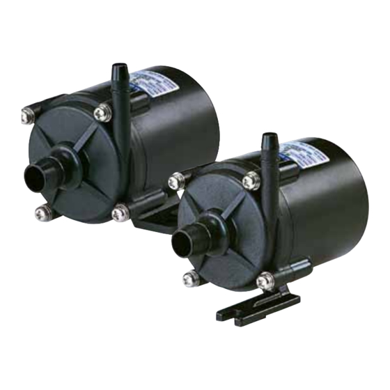
TOKYO, JAPAN Operating Principle The RD Series pump is a canned motor type centrifugal pump driven by a DC brushless motor. The magnet incorporated with the impeller is directly rotated in the pump chamber by the magnetic force of the motor to discharge the liquid from suction port to the discharge port. -
Page 4: Model Identification Guide
FKM (as an option on RD-12/12Z) EPDM Power source voltage 24VDC 12VDC option available for OEM applications, contact Iwaki America for details. Liquid Temperature Rating No Symbol: 0 - 40 °C (RD-12, 12Z 0-60°C) 60°C High temperature 0 – 80°C... - Page 5 RD - 40 24 - Pump size 40, 40X 2 O ring material V: FKM E: EPDM 3 Power source voltage 24: 24VDC 4 Liquid Temperature range H: High Liquid Temperature 0 – 80°C 5 Connection No symbol: Hose R1: R Thread N1: NPT thread V:1 –...
-
Page 6: Specifications
Specifications Connections (Hose) Motor Max flow Max head Weight Model Specific Suction Discharge Rated output FT (m) Lbs (kg) Power (V) (L/min) Gravity Inches (mm) Inches (mm) RD-05 0.55 (14) 0.32 (8) 1.2 (4.7) 11.8 (3.6) DC24 0.9 (0.4) RD-05H 0.55 (14) 0.32 (8) 2.1 (7.9) -
Page 7: Main Parts
Main Parts Pump unit (Liquid feeding unit) Discharge port Specifications label Use the pump according to the specifications on the label. Suction port Base Fix the pump securely. -
Page 8: Dimensions
Dimensions (58) RD-05/12(Z) RD-05H (12) (50) (121) (106) RD-20/30 RD-40(X) (15) Dimensions in inches (mm) Model 2.99 2.95 3.72 0.63 1.18 2.52 1.18 1.16 0.88 1.98 RD-05 2-5x7 (76) (75) (94.5) (16) (30) (64) (30) (29.5) (22.4) (50.5) 2.28 3.07 4.25 3.54 3.94... -
Page 9: Handling Instructions
Handling Instructions Warning Switch off the power when the pump or its electrical parts get wet. Keep the pump away from fire Do not place dangerous or flammable substances near the pump. Caution Keep the impeller assembly away from any electronic device that could be affected by a strong magnetic field. -
Page 10: Installation, Piping And Wiring
7. Power cable A broken or frayed power cable may cause an electrical shock. Do not bend, pull or twist power cords. Consult Iwaki America customer service if power cable is damaged and needs to be replaced. 8. Cleaning the pump Do not clean the exterior of the pump with a solvent such as Benzene, alcohol, etc. -
Page 11: Piping Instructions
Pump base mounting The base of the pump must be anchored firmly to the mounting surface. It is recommended that the unit be installed in a horizontal position, however vertical mounting is acceptable provided adequate liquid level above inlet is present and air is properly vented. Piping Instructions ... -
Page 12: Wiring
Caution Do not tighten the connection ports (suction and discharge) excessively as they are made of plastic resin and are easily damaged. Hose Clamp Pay attention the load is not applied to inlet and outlet port. Wiring Before you start wiring works, make sure the main power is switched off. ... -
Page 13: Operation
If pump is switched ON and OFF, install the switch at the secondary side of DC power source (between power sources and pump). If power is ON and OFF at the primary side of DC power source, it is possible pump can not start. Good No good DC power... -
Page 14: Operation
Operation After the installation, piping and wiring processes are completed, operate the pump in accordance with the following steps. Operation Step Description (Points to be checked) Check in accordance with the ‘Hose connection’ Check piping, wiring and and ‘Wiring’ sections. Check the power supply voltage voltage by referring to the information on the nameplate. -
Page 15: Pump Stopping Procedures
Pump Stopping Procedures Stopping Step Description Close discharge side valve Close discharge side valve gradually. Do not use electromagnetic valve for quick closing. Turn off power supply. (Check Check that motor stops smoothly stopping condition.) after power is disconnected. If not, pump should be inspected. -
Page 16: Draining Procedure
Draining procedure 1. Turn off the power supply. (Make sure no other operator will turn on the power supply accidentally.) 2. Fully close the discharge and suction sides valves. 3. Remove the hoses connected with the discharge and suction ports. Position the draining pan below the pump unit in advance. -
Page 17: Troubleshooting And Maintenance
Troubleshooting and Maintenance Electric Excessive Excessive Pump does Insufficient current Liquid Cause noise or Troubleshooting heat not start pumping is too leaks vibration high Check and correct Power is not supplied or wiring is faulty wiring Motor is out of order (disconnect coil or ... -
Page 18: Parts Description
Parts Description & Materials 05, 05H 12, 12Z 20, 30 40, 40X 1 Casing GFRPPE GFRPPS GFRPPS 2 Rear casing GFRPPE GFRPPS GFRPPS 3 Impeller GFRPP GFRPPS GFRPP GFRPPS 4 Spindle Alumina Ceramic 5 Bearing PTFE/PPS PTFE PTFE PTFE 6 Thrust ring Alumina Ceramic 7 O-ring FKM or EPDM...
Need help?
Do you have a question about the RD Series and is the answer not in the manual?
Questions and answers