
Summary of Contents for Ahlborn Almemo KA 7531
- Page 1 ____________________________ Operating instruction English Simulator ALMEMO ® KA 7531 V1.4 03.12.2012 www.ahlborn.com...
-
Page 2: Operating Controls
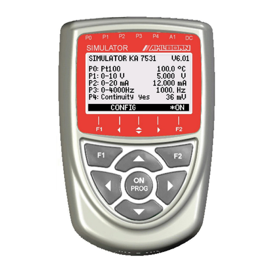
1. Operating Controls 1. OPERATING CONTROLS (1) Signal sockets P0 to P4 for ALMEMO ® clamp connectors P0 Pt100 P1 10V, 60mV, thermocouples P2 20mA P3 Digital signals P4 Continuity check (2) Output socket A1 A1 V24 Interface (ZA 1909-DK5) USB (ZA 1919-DKU) LWL (ZA 1909-DKL) Ethernet (ZA 1945-DK) -
Page 3: Table Of Contents
Table of Contents 2. TABLE OF CONTENTS 1. OPERATING CONTROLS................2 3. GENERAL..................... 4 3.1 Warranty....................4 3.2 Standard delivery................4 3.3 Waste disposal..................5 4. SAFETY INSTRUCTIONS................5 4.1 Special notes on use................5 4.2 Handling batteries / rechargeable batteries correctly......5 5. THE SIMULATOR FUNCTIONS..............6 6. -
Page 4: General
3. general 3. GENERAL Congratulations on your purchase of this new and innovative ALMEMO ® simu- lator. It will allow you to perform a wide range of simulation runs on sensors and transmitters and put data acquisition and automation systems into service quickly and easily. -
Page 5: Waste Disposal
Waste disposal 3.3 Waste disposal This symbol means that the product is subject to European Union regulations on segregated waste disposal. This applies both to the product itself and to any accessories marked with the same symbol. Disposal of any such item as unsorted do- mestic waste is strictly forbidden. -
Page 6: The Simulator Functions
5. The simulator functions 5. THE SIMULATOR FUNCTIONS Simulator ALMEMO ® KA7531 is a universal generator of sensor and transmit- ter variables. For Pt100 sensors it incorporates 5 precision resistors in 4-con- ductor circuitry. Voltage signals from 7 different thermocouple types with set- table cold junction temperature are calculated and output via a 16-bit D/A con- verter. -
Page 7: Power Supply
Power supply 7. POWER SUPPLY Power can be supplied to the simulator in any of the following ways : 3 AA alkaline batteries, in the device Mains adapter 12 V, 0.2 A, with ALMEMO ® connector ZA1312NA1 External DC voltage, 10 to 30 V via ALMEMO ®... -
Page 8: Display And Operating Controls
8. Display and operating controls 8. DISPLAY AND OPERATING CONTROLS The simulator incorporates a keypad (4) and a SIMULATOR KA 7531 V6.01 graphic display (5) for the purposes of configur- P0: Pt100 100.0 °C ing the device and operating all signals. The P1: 0-10 V 5.000 V main menu shows the associated ports P0 to P4... -
Page 9: Menus
Data entry To change the arithmetic sign < +/- > To select the next position ► The cursor blinks below the second digit. P1: 0-10V: 10.000 V To move back to the previous digit ◄ Each position is programmed like the first.., ▲... -
Page 10: Voltage Output, Thermocouples
9. Menus 9.2.2 Voltage output, thermocouples The voltage output is present at socket P1. see6. P1: Output 0 - 10V In associated submenu P1 the following voltage Function steps automatically ranges can be selected: 5.000 V -3 to 10V, -10 to 60mV Step: 01.000 V Fª... -
Page 11: Digital Signal Output
Submenus 9.2.4 Digital signal output Frequencies For frequencies and pulses socket P3 is pro- P3: Output Frequency 4000Hz vided. In submenu P3 the following can be se- Function: steps individually 1000 Hz lected : 4 frequency ranges 1 to 4000 Hz, Pulse width: 50.0 % 1 to 10.00 kHz... -
Page 12: Simulator Functions
9. Menus 9.3 Simulator functions To run a quick and easy check on a control process or a control element vari - ous values can be systematically specified either in steps or automatically in ramp form. To do this select the ´Function´ line (see 8.1). Program one of the available functions Steps manual Steps automatic... -
Page 13: Device Configuration
Device configuration 9.4 Device configuration In the menu ´DEVICE CONFIGURATION´ certain * DEVICE CONFIGURATION * basic settings for the adapter can be made. Device address: 00 Baud rate: 9600 Bd namely the operating parameters ´Device ad- Language: English dress´ and ´Baud rate´ for the serial interface, Illumination: Øduration: 20sec Contrast: 50 % UBat: 4.5 V... -
Page 14: Serial Interface
9. Menus 9.4.5 Device address To communicate with networked devices it is absolutely essential that all the devices concerned should have the same baud rate setting but that each should have its own dedicated address; this is because only one device should respond per command. -
Page 15: Programming Via The Interface
Programming via the interface 10.1 Programming via the interface To program a function Command Port 01 range V Port 01 range mV Port 01 range TC type K Port 01 range TC type N Port 01 range TC type J Port 01 range TC type T Port 01 range TC type S Port 01 range TC type R... -
Page 16: Electromagnetic Compatibility
11. Electromagnetic compatibility 11. ELECTROMAGNETIC COMPATIBILITY Ahlborn Mess- und Regelungstechnik GmbH declares herewith that measuring instrument ALMEMO ® KA 7531 carries the CE label and complies in full with the requirements of EU directives relating to low voltage and to electromag- netic compatibility (EMC) (89/336/EWG). -
Page 17: Appendix
Appendix 12. APPENDIX 12.1 Technical data Pt100 5 resistors in 4-conductor circuitry, electr. isolated Temperature values 0, 50, 100, 200, 300 °C Accuracy ±0.1 °C Temperature drift 0.01 °C/K Analog outputs Electr. isolated Resolution 15 bits -4.0 to +10.000 V Load >100 kΩ... -
Page 18: Index
12. Appendix 12.3 Index 4-conductor circuitry Accessories 12.2 Accuracy 12.1 Analog outputs 12.1 available operating voltage Battery operation Battery voltage 9.4.3 Baud rate 9.4.4 cold junction temperature 9.2.2 Connecting the simulator Continuity check 12.1 11, 17 contrast 9.4.2 current consumption Current consumption 12.1 Current output... - Page 19 Index Power supply 12.1 7, 17 Programming via the interface 10.1 Pt100 12.1 Pt100 output 9.2.1 pulse / pause ratio 9.2.4 pulse duration 9.2.4 pulse range 9.2.4 Pulse ranges 12.1 pulse width 9.2.4 Ramp 9.3.3 reinitialization Remote Control replace old batteries Safety instructions select a function Serial interface...
-
Page 20: Your Contact Partner
13. Your contact partner 13. YOUR CONTACT PARTNER AHLBORN Mess- und Regelungstechnik GmbH Eichenfeldstraße 1 83607 Holzkirchen Germany internet : http://www.ahlborn.com e-mail : amr@ahlborn.com Even the greatest possible care cannot exclude the possibility of inaccuracies. We reserve the right to make technical changes without advance notice.
Need help?
Do you have a question about the Almemo KA 7531 and is the answer not in the manual?
Questions and answers