
Subscribe to Our Youtube Channel
Summary of Contents for Isel ISY 3DSCAN
- Page 1 Getting Started Guide Version 1.1 Isel Germany AG Untere Roede 2 | D-36466 Dermbach Germany Phone: +49(0)36964-84500 | Fax: +49(0)03964-84510 Mail: info@isel.com | Web: www.isel.com © 2012 Isel Germany AG...
-
Page 2: Contents Of Package
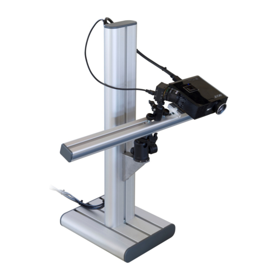
Do not operate the scanner in areas where there is a risk of explosion. Repairs to the scanner or its components may only be performed by an authorized service centre or the ISEL after-sales service. Do not make changes of any kind to your scanner. - Page 3 Preparation Setup 20-25° distance distance (side view) (top view) Before connecting the devices, adapt the whole scanner setup to the size of the object or surface region you want to scan. The intersection angle between projection and camera view should be around 20°-25° (max. 15°- 35°).
-
Page 4: Installation
Installation Connect all components as depicted below: VGA / HDMI Installation of the Camera Drivers 1. Plug the USB drive into your PC, then choose “Open” resp. “Explorer”. 2. Launch “Install_CCD-Camera_Driver“ (may require administrator rights). 3. Follow the instructions on screen. Projector Settings The projector is shipped with optimal settings. - Page 5 Setup Projector as Extended Desktop in Windows With your right mouse button, click on a free space on your Windows desktop. Choose “Resolution” or “Properties” (depending on your Windows version). In this dialogue window, you can separately change the settings of your two displays, monitor and projector.
- Page 6 Scanning with ISY 3D SCAN Launch ISY 3D SCAN by starting “Start_ISY 3D SCAN “ on your USB key. On the left side you can see the expandable main menus. Each menu is dedicated to one of the following work steps, which you will usually walk through from top to bottom. For the individual work steps, different camera and/or projector settings may be optimal.
- Page 7 8. Adjust the mechanic aperture at the camera's lens. Regard only those image regions that show the circular wave pattern: The red intensity curves must be sinusoidal and must not be over- or under-saturated. In other words, the red sine curve must not be cut off at the blue borders.
- Page 8 camera should not able to look past the calibration boards. You can move, rotate and tilt the scanner as a whole, but you should not change anything above the red mounting rack. 3. Enter the scale size of the calibration pattern at “Calibr. Scale”. You can find the number printed on the panels right next to the respective pattern.
- Page 9 5. Click “Calibrate“ in order to calibrate the camera. In this step the software computes the position and orientation of the camera, as well as the focal length and distortion parameters of its lens. 6. From this moment on, do not move or adjust anything at the scanner – otherwise you will have to repeat the calibration.
- Page 10 3D Scanning Menu “Structured Light Scanning“ Place scanner and object in front of each other, like you did during calibration. If the distance is too different, the projected stripes and camera image will be out of focus. In this case, correct the distance, not the focus rings. Important: For each scan, observe that the red sine waves are not cut off / overdriven (this refers only to the image regions where the circular wave pattern is visible).
- Page 11 With your mouse, you can rotate, move and zoom the 3D view. The scans need to overlap sufficiently so that they can be combined/aligned later on. Generally, 6-8 scans of different views around an object are required, plus possibly a few of the top and bottom sides.
-
Page 12: Alignment And Fusion Of Multiple Scans
Alignment and Fusion of Multiple Scans Menu “Shape Fusion“ This menu offers to 1. align several scans to each other and 2. fuse them to one closed 360° model. You can export the fused object in various file formats and use it e.g. for 3D printing. In the following we describe the general case of aligning scans from arbitrary perspectives. - Page 13 Hint: All scan movements can be undone separately with the “Undo” button Hint: You can save your single scans at any time. They will be saved in their current position and rotation in space, so you won't have to align them again. Hint: After some alignment steps it can be helpful to “combine”...
-
Page 14: Terms Of Warranty
After the warranty period has expired you still have the option of sending the defective device to your supplier or to the ISEL after-sales service for repair. Repairs made after expiry of warranty will be subject to a charge. Your statutory rights are not affected through this warranty.
Need help?
Do you have a question about the ISY 3DSCAN and is the answer not in the manual?
Questions and answers