Summary of Contents for GF Modbus RTU
- Page 1 GF Piping Systems Instruction manual Modbus RTU Interface board for Electric Actuators Type EA25 - EA250 700278135 MA_00044_EN_1a (08.20) © Georg Fischer Piping Systems Ltd 8201 Schaffhausen/Schweiz, 2020...
-
Page 2: Table Of Contents
Instruction manual Contents Intended use About this document Warnings Further symbols and labels Other applicable documents Abbreviations Safety information Modbus RTU board installation Modbus RTU interface description Introduction Supported Function Codes Slave Address Modbus Register Map Modbus board configuration... - Page 3 Instruction manual Original operating manual Disclaimer The technical data are not binding. They neither constitutes expressly warranted characteristics nor guaranteed properties nor a guaranteed durability. They are subject to modification. Our General Terms of Sale apply. Observe instruction manual The instruction manual is part of the product and an important element within the safety concept. ►...
-
Page 4: Intended Use
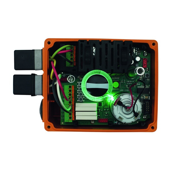
Instruction manual Intended use The Modbus RTU is used to upgrade Electric GF Acutators Type EA25, EA45, EA120 and EA250 with the Modbus interface. The board has to be installed into the designated slot of the actuator. This board can be used for 24 VAC/DC as well as for 100-230 VAC actuator versions. -
Page 5: Safety Information
► Separate materials (plastics, metals, etc.) and dispose of them in accordance with local regulations. A product marked with this symbol must be disposed of in the separate collection of electrical and electronic equipment. If you have any questions regarding the disposal of the product, please contact your national GF Piping Systems representative. -
Page 6: Modbus Rtu Board Installation
Instruction manual Modbus RTU board installation CAUTION! Danger due to energized actuator! Injuries due to electric shock or moving parts while open actuator case. ► Disconnect the actuator from the power supply! CAUTION! Caution when handling the board! Electrostatic discharge can damage the components. - Page 7 Instruction manual Place the Modbus RTU board into the free slot. Make sure that the board is correctly snapped into the guide rails. CAUTION STATIC DISSIPATIVE OBSERVE PRECAUTIONIS FOR HANDLING ELECTROSTATIC SENSITIVE DEVICES Insert the Modbus RTU connection cable into the cable union and connect the glands D0, D1 and COM to the connector on the board.
-
Page 8: Modbus Rtu Interface Description
System), HMI (Human Machine Interface), RTU (Remote Terminal Unit) or PC. The Modbus RTU interface board fits into the option slot 1 (X6) of the EA25-250 and EAMT25- 100 baseboards. It supports the Modbus RTU protocol via 2 wire RS-485 serial communication standard. -
Page 9: Modbus Register Map
Instruction manual Modbus Register Map This chapter describes the format of the data contained in the supported Modbus messages. 5.4.1 Registers used during normal operation Parameter Address (hex) Reg. Size Read/Write Unit Type Description TYPVLT 0x0000 UINT8 Type and voltage info POSACT 0x0001 UINT8... - Page 10 Instruction manual 5.4.3 POSACT Byte-Name: POSACT Bit 7 Bit 6 Bit 5 Bit 4 Bit 3 Bit 2 Bit 1 Bit 0 <position_actual_value> <position_actual_value> range = 0…100% 0 = position_closed 100 = position_open 255= position_invalid 5.4.4 STATE Byte-Name: STATE Bit 7 Bit 6 Bit 5 Bit 4...
- Page 11 Instruction manual 5.4.8 ERRFLAGS Label: ERRFLAGS High Word Low Word Reg.# 40009 (Adr. 8) Reg.# 40008 (Adr. 7) Double-Word = 32Bit-Value. <error_flags> 0 means no error/warning asserted. Else: Name Description undervoltage Undervoltage condition / seven segment 'U' over_temp_case Over temperature inside EA / seven segment 'O' max_positioning_time Time monitoring / seven segment ‘S’...
- Page 12 Instruction manual 5.4.10 ACKRST Control Byte to acknowledge error and reset cycle counter. Byte-Name: ACKRST Bit 7 Bit 6 Bit 5 Bit 4 Bit 3 Bit 2 Bit 1 Bit 0 Action reserved reserved reserved reserved reserved reserved cycle_ error_ack cntr_reset reset_cycle_counter error_ack...
- Page 13 Instruction manual 5.4.13 BCDSET0 Cycle time extension and cycle time monitoring. Byte-Name: BCDSET0 Bit 7 Bit 6 Bit 5 Bit 4 Bit 3 Bit 2 Bit 1 Bit 0 <cyc_time_mon_bcd> <cyc_time_ext_bcd> <cyc_time_ext_bcd> Min: 0 Max: 9 Default: 0 Description: Extents the time for a movement of typical 90°. Positioning speed can be reduced with this setting.
- Page 14 Instruction manual 5.4.15 NSIGACT Action on loss of signal (setup of busfault reaction). Byte-Name: NSIGACT Bit 7 Bit 6 Bit 5 Bit 4 Bit 3 Bit 2 Bit 1 Bit 0 reserved reserved reserved reserved reserved reserved < signal_loss_action> <signal_loss_action> <signal_loss_action>...
-
Page 15: Modbus Board Configuration
Register # 49001 refers to register holding register address 9000 (2328(hex)). The Modbus RTU board configuration can be reset to its default values (see Table above) by triggering a factory reset on the Electric Actuator base-board (see user manual of the Electric... - Page 16 GF Piping Systems Worldwide at home Our sales companies and representatives ensure local customer support in more than 100 countries. www.gfps.com Argentina / Southern South America France Mexico / Northern Latin America Singapore Georg Fischer Central Plastics Sudamérica S.R.L. Georg Fischer SAS Georg Fischer S.A.


Need help?
Do you have a question about the Modbus RTU and is the answer not in the manual?
Questions and answers