
Subscribe to Our Youtube Channel
Summary of Contents for Vanguard Instruments MCCB-250
- Page 1 MCCB-250 MOLDED-CASE CIRCUIT BREAKER TESTER USER’S MANUAL Vanguard Instruments Company, Inc. 1520 S. Hellman Ave. Ontario, California 91761, USA TEL: (909) 923-9390 January 2015 FAX: (909) 923-9391 Revision 2.1...
- Page 2 MCCB-250. The following safety precautions must be observed during all phases of test setup, test hookups, testing, and test lead disconnection. SAFETY WARNINGS AND CAUTIONS The MCCB-250 shall be used only by trained operators. All circuit breakers under test shall be off-line and fully isolated. SERVICE AND REPAIR •...
-
Page 3: Table Of Contents
Measuring Current Transformer Primary and Secondary Currents ......13 LIST OF TABLES Table 1. MCCB-250 Technical Specifications .................. 3 Table 2. Functional Descriptions of MCCB-250 Controls and Indicators ........5 Table 3. MCCB-250 Current Output ....................6 Table 4. MCCB-250 Overload Current Output ................6 LIST OF FIGURES Figure 1. -
Page 4: Conventions Used In This Document
MCCB-250 USER’S MANUAL REV 2 CONVENTIONS USED IN THIS DOCUMENT This document uses the following conventions: A key, switch, input, or knob on the MCCB-250 is indicated as [KEY], [SWITCH], • [INPUT], [KNOB] Menu options are referenced as (MENU OPTION). -
Page 5: Introduction
MCCB-250 Current Source The MCCB-250 has 4 current-source outputs (5 A @ 120 Vac, 25 A @ 24 Vac, 120 A @ 6 Vac, 250 A @ 3 Vac) that conduct the test current through the high-impedance load circuits. Each current source can tolerate short-duration over-loads up to 4 times the rated current. -
Page 6: Mccb-250 Technical Specifications
MCCB-250 USER’S MANUAL REV 2 MCCB-250 Technical Specifications Table 1. MCCB-250 Technical Specifications TYPE 250 Ampere current source PHYSICAL SPECIFICATIONS Dimensions: 16.8”W x 12.6”H x 10.6”D (42.6 cm x 32.0 cm x 27.0 cm); Weight: 46 lbs (21 kg) 100 – 120 Vac or 200 – 240 Vac (factory pre-set), 50/60 Hz INPUT POWER OUTPUT CURRENTS 0 –... -
Page 7: Controls And Indicators
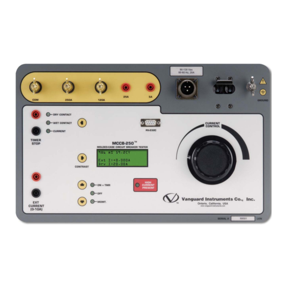
MCCB-250 USER’S MANUAL Controls and Indicators The MCCB-250’s controls and indicators are shown in Figure 1. A leader line with an index number points to each control and indicator, which is cross-referenced to a functional description in Table 2. The table describes the function of each item on the control panel. The purpose of the controls and indicators may seem obvious, but users should become familiar with them before using the MCCB-250. -
Page 8: Table 2. Functional Descriptions Of Mccb-250 Controls And Indicators
90-120 Vac Input power connector. 50-60 Hz, 20A 200-240 Vac 50-60 Hz, 20A None Circuit Breaker/Power Switch. MCCB-250 ground stud. Connect ground stud to substation ground using GROUND provided cable. CURRENT Current control knob. CONTROL HIGH High current presence indicator LED. -
Page 9: Functional Description
MCCB-250 USER’S MANUAL FUNCTIONAL DESCRIPTION MCCB-250 AC Current Source The MCCB-250 provides five AC current outputs (items 1, 2, 3, 4, and 5 in Figure 1). AC test current is set by the knob. This test current is measured and [CURRENT CONTROL] displayed on the LCD screen. -
Page 10: Mccb-250 Current Output Control
The LED indicator next to the “MOMT” label will turn on indicating that the MCCB-250 current source is on. The output current will also be displayed on the LCD screen. The MCCB-250 current output can now be set by turning the [CURRENT CONTROL] knob. -
Page 11: Timer Stop Input And Control
A change in this dry contact state will stop the timer and turn off the current source. In WET CONTACT mode, the MCCB-250 will sense an AC or DC voltage applied to the [TIMER STOP] terminals. -
Page 12: Mccb-250 Timer
REV 2 MCCB-250 Timer The MCCB-250’s built-in time/cycle counter can be used to time events in milliseconds and cycles. The elapsed time is displayed on the LCD screen along with the test current after a test is completed. A typical test results screen is shown in Figure 2. The timer is turned on when the ON+TMR mode is selected. - Page 13 MCCB-250 USER’S MANUAL 50/60 Hz Cycle Time Selection When the MCCB-250 is turned on, the cycle time setting (50 Hz or 60 Hz) will be displayed on the LCD screen during the start-up sequence. To toggle the cycle time setting, first make sure the unit is turned OFF, then hold down the key to the left of the LCD screen and then turn on the power.
-
Page 14: Operating Procedures
Figure 3 illustrates a typical connection of the MCCB-250 to a protection relay to test its “Open Time Delay”. The MCCB-250 injects a test current through a bus. The test current is sensed by the CT of the protection relay. One of the relay dry contacts is used to stop the MCCB-250 timer. - Page 15 Use the steps below to test the time delay of a protection relay: a. Connect the Safety Ground to the MCCB-250. b. Connect the AC power cord. c. Connect the Current Cables from the MCCB-250 to the bus as shown in Figure 3. d. Connect the [TIMER STOP] cables as shown in Figure 3.
-
Page 16: Measuring Current Transformer Primary And Secondary Currents
REV 2 Measuring Current Transformer Primary and Secondary Currents Figure 4 shows a typical connection of the MCCB-250 to a current transformer. In this configuration, the MCCB-250 injects a test current through the CT primary. The CT secondary current is sensed by the MCCB-250’s input. - Page 17 Follow the steps below to measure the CT primary and secondary currents: a. Connect the Safety Ground to the MCCB-250. b. Connect the Current cables from the MCCB-250 to the bus (CT primary) as shown in Figure 4. c. Connect the CT secondary winding to the MCCB-250...
- Page 18 1520 S. Hellman Ave • Ontario, CA 91761 • USA Phone: 909-923-9390 • Fax: 909-923-9391 www.vanguard-instruments.com Copyright © 2009 by Vanguard Instruments Company, Inc. MCCB-250 User’s Manual • Revision 2.1 • January 7, 2015 • TA...
Need help?
Do you have a question about the MCCB-250 and is the answer not in the manual?
Questions and answers