
Related Manuals for ENDEVCO 436


Summary of Contents for ENDEVCO 436
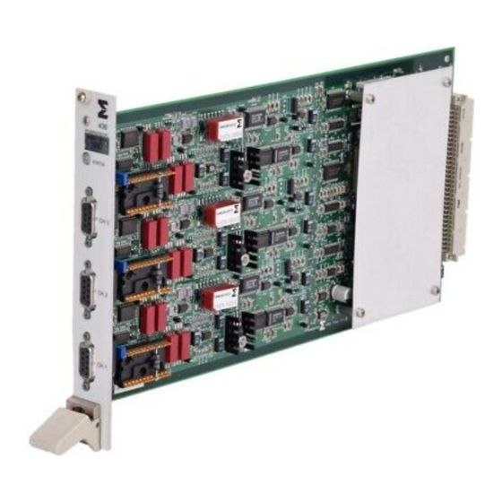
- Page 1 MODEL 436 Three Channel DC Differential Signal Conditioner INSTRUCTION MANUAL San Juan Capistrano, California, USA IM436 REVISION A March 1, 2000...
- Page 2 ENDEVCO MODEL 436 INSTRUCTION MANUAL GENERAL DESCRIPTION 1. SYSTEM OVERVIEW 2. MANUAL ORGANIZATION 3. SPECIFICATIONS LECTRICAL HARACTERISTICS NPUTS LECTRICAL HARACTERISTICS UTPUTS TRANSFER CHARACTERISTICS POWER REQUIREMENT PHYSICAL CHARACTERISTICS ENVIRONMENTAL CHARACTERISTICS 4. EQUIPMENT SUPPLIED INSTALLATION AND OPERATION 1. INTRODUCTION 2. UNPACKING AND INSPECTION 3.
- Page 3 ENDEVCO MODEL 436 INSTRUCTION MANUAL 6. SAFETY 7. ROUTINE MAINTENANCE AND HANDLING A. I NTRODUCTION B. F ACTORY ERVICE C. WARRANTY D. OUT-OF-WARRANTY RETURNS APPENDIX 1 PS436 APPENDIX 2 PS31875 IM436...
-
Page 4: General Description
5, 10, 15 VDC. The Endevco Model 436 Signal Conditioner card is designed to be used with the Endevco Model 4990 (RS-232 or Ethernet option) 19” Rack. The Endevco Model 436 can be remotely programmed by using the controller software model 4991. - Page 5 ENDEVCO MODEL 436 INSTRUCTION MANUAL 200 Ω or less input imbalance, DC to 60 Hz Input Imbalance Adjustment ±100 mVDC, 100 < gain < 1000 ±1 VDC, 10 < gain < 100 ±10 VDC, 0 < gain < 10 Calibration Input High impedance, single-ended, DC-coupled with one side connected to signal ground.
- Page 6 ENDEVCO MODEL 436 INSTRUCTION MANUAL TRANSFER CHARACTERISTICS Gain Range Programmable from 0 to 1000 Resolution 0.0025, 0 < gain < 10 0.025, 10 < gain < 100 0.25, 100 < gain < 1000 Accuracy ±0.5% of full scale maximum DC to 1 kHz, filters disabled.
-
Page 7: Power Requirement
ENDEVCO MODEL 436 INSTRUCTION MANUAL POWER REQUIREMENT Voltage Requirement +5VDC, ±15 VDC, +24 VDC Current Consumption (typical, excitation = 0VDC) +5VDC: 75mA +24VDC: 47mA +15VDC: 100mA -15VDC: 160mA Power Dissipation 5.42 Watts typical Plus up to 2 Watts per Channel to power sensor. -
Page 8: Equipment Supplied
ENDEVCO MODEL 436 INSTRUCTION MANUAL EQUIPMENT SUPPLIED Description Endevco Quantity Part No. Supplied Instruction Manual IM436 4-Pole Lowpass Filter Header Module 31875- 1000 9-pin “D” Mating Connector Kit 29719-2 Shunt Calibration & Bridge 31874 Completion Adapter Resistor Header for 4-pole Lowpass... -
Page 9: Unpacking And Inspection
WARNING OBSERVE SOUND ESD PRECAUTIONS WHEN UNPACKING AND HANDLING THE MODEL 436 The Model 436 has been thoroughly tested at the factory before shipment and should be ready for operation when received. However, an inspection should be made to ensure that no damage occurred during shipment. - Page 10 ENDEVCO MODEL 436 INSTRUCTION MANUAL A. Baud Rate and Signal Routing Selection Baud Rate and Signal Routing is selected through two 8-position DIP switches, located on the card-side of the back plane, accessible from the front side of the unit. To access the DIP switches, the card in slot 16 has to be removed.
- Page 11 ENDEVCO MODEL 436 INSTRUCTION MANUAL C. Default Jumper Settings for Ethernet Rack (4990-1): REMARK REMARK SWITCH SWITCH SETTING SETTING (ON for snoop mode) EDAS RX back plane RX (ON for snoop mode) (ON for snoop mode) (ON for snoop mode) EDAS TX ...
- Page 12 ENDEVCO MODEL 436 INSTRUCTION MANUAL D. Optional Jumper Settings for EDAS Configuration only (4990-1): REMARK REMARK SWITCH SWITCH SETTING SETTING EDAS RX front panel RX EDAS TX front panel TX EDAS RX front panel RX EDAS TX ...
- Page 13 Power up the Model 4990 by activating the switch on the power entry module. Verify the fan is operating and the fan filter is in place. Verify the LED on the front of the Model 436 is lit. CAUTION: The channel settings of the signal conditioning modules are not automatically stored in non volatile memory.
- Page 14 The software can configure up to a maximum of 16 racks with up to 16 units in each rack. If 16 racks contained 16 Model 436 units then the channel count would be 768 (16x16x2). The racks needn’t however, contain the same unit type in each slot of each rack.
- Page 15 The same set of functions and modes are available for each channel. H. Functional Characteristics Model 436 is fully compatible with the 400-series specifications, i.e. it is designed to operate in both the Model 4990-2 (via a standard RS-232 serial interface) and the Model 4990-1 Rack (via Ethernet).
- Page 16 ENDEVCO MODEL 436 INSTRUCTION MANUAL I. Sensor Connections One Remote PR Sensor (Full Bridge), 6-Wire Connection Two Remote PR Sensors (Half Bridge), 3-Wire Connection IM436...
- Page 17 ENDEVCO MODEL 436 INSTRUCTION MANUAL Two Remote PR Sensors (Half Bridge), 2 Sets of 3-Wire Connection Two Remote PR Sensors (Half Bridge), 2 Sets of 4-Wire Connection IM436...
- Page 18 K. Communication with the OASIS 2000 Software Model 436 is fully compatible with the 400-series specifications, i.e. it is designed to operate in a Model 4990-2 Rack (via a standard RS-232 serial interface) or in a Model 4990-1 Rack (via Ethernet).
- Page 19 Gain < 1000 constraint. P. Output Scaling This function selection provides for programming the desired scaling of the amplifier’s output (in mV/EU). The Endevco Model 436 determines the gain needed to achieve the required output scaling by using the following equation: Output Scaling Full Scale Output Range Amplifier’s Gain =...
- Page 20 If the Full Scale Output Range is incremented to the point where Amplifier’s Gain is greater than 10000, then the 436 amplifier will temporarily set an error message to indicate that the Full Scale Input Range has been modified to meet the Gain < 10000 constraint (Maximum Gain Limit Error).
- Page 21 ENDEVCO MODEL 436 INSTRUCTION MANUAL R. Operation Modes (OFF, Auto-Zero, Auto-Balance, Out-Cal) The following options for mode selection are available:. "OFF": The unit sets all of the internal DC offset adjustments to neutral. "Execute Zero": The unit short its inputs to ground and sets the DC output voltage to zero to within ±10 mVDC (zero will depend on the DC voltage imbalance present at the...
- Page 22 Calibration Constants A table of all calibration constants used by the 436 firmware is shown below. The calibration constants are stored in the EEPROM of the unit. A checksum for the calibration constants is stored in non-volatile memory. The card will use this checksum at power up to verify that all calibration constants are good.
- Page 23 They do not have to be calibrated manually. Calibration Procedure Each Model 436 unit shipped by ENDEVCO ® has been calibrated in the factory. The calibration of the unit can easily be checked by applying a known input voltage at a given gain and measuring the output voltage.
- Page 24 ENDEVCO MODEL 436 INSTRUCTION MANUAL Adjusting Calibration Constant: K3 (Gain=0…10) 1. Set channel 1's Gain=2, LPF off 2. Read the current calibration constant for this gain range and this channel (K 3. Apply input voltage Vin=3.5Vrms @ 300 Hz 4. Measure output voltage V 5.
- Page 25 LED will flash briefly every five seconds. AB. Code Download The Model 436 is capable of downloading new operational code via the serial interface. This is achieved through a bootloader program implemented in the EEPROM section of the PSD813F1 memory device.
- Page 26 To aid in troubleshooting the rack, access to the power supply and module interconnect PCB is gained with the rear panel dropped down to the open position. If 4990 or 436 do not respond, check: • Power applied to 4990 rack. Check fuse. Fan must be audible, air flow must be present.
- Page 27 Failure to comply with these precautions or with specific warnings elsewhere in this manual violates safety standards of design, manufacture, and intended use of the instrument. ENDEVCO assumes no liability for the customer’s failure to comply with these requirements.
- Page 28 ENDEVCO MODEL 436 INSTRUCTION MANUAL Line Fuse Verify that the correct line fuse is installed before connecting the line cord. IM436...
-
Page 29: Routine Maintenance And Handling
ENDEVCO for repair/replacement. Should a faulty unit be returned to Endevco, it is suggested that the original or equivalent packaging be used. This will reduce damage to the equipment during shipment. - Page 30 ENDEVCO MODEL 436 INSTRUCTION MANUAL APPENDIX 1 PS436 IM436...
- Page 31 ENDEVCO MODEL 436 INSTRUCTION MANUAL APPENDIX 2 PS31875 IM436...
Need help?
Do you have a question about the 436 and is the answer not in the manual?
Questions and answers