
Related Manuals for MEN BL51E

Summary of Contents for MEN BL51E
- Page 1 20BL51E00 E2 2020-03-27 BL51E Rugged Box PC for Transportation with Intel Atom Processor E3900 Series Embedded Computer for Communication & Control User Manual...
-
Page 2: Table Of Contents
Using the BL51E under Windows ........ - Page 3 Contents 2.9.5 Configuring Wireless Functions ......41 2.9.6 Switching Serial Interfaces ....... . . 42 3 Functional Description.
- Page 4 SMBus/I2C Devices ..........83 5.1.1 BL51E Information EEPROM....... . 84 5.1.2 SMBus Configuration Registers .
- Page 5 Functions in the MEN Menu ........
- Page 6 Contents Table 68. SMBus/I2C – Board information EEPROM – address map ....84 Table 69. SMBus/I2C – Board information EEPROM – byte structure of production data Table 70.
-
Page 7: About This Document
This document is intended only for system developers and integrators. It describes the design, functions and connection of the product. The manual does not include detailed information on individual components (data sheets etc.). BL51E product page with up-to-date information and downloads: www.men.de/products/bl51e/ History... - Page 8 About this Document Conventions Indicates important information or warnings concerning situations which could result in personal injury, or damage or destruction of the component. Indicates important information concerning electrostatic discharge which could result in damage or destruction of the component. Indicates important information or warnings concerning proper functionality of the product described in this document.
-
Page 9: Product Safety
Only store the product in its original ESD-protected packaging. Retain the original packaging in case you need to return the product to MEN for repair. 20BL51E00 E2 2020-03-27 Page 9 ... -
Page 10: Product Compliance
If the product delivered was certified by MEN and is modified by the customer, e.g., by installing an additional hardware component, the certification achieved by MEN becomes invalid and may have to be repeated for the new product configuration. -
Page 11: Disclaimer
MEN was negligent regarding the design or manufacture of the part. In no case is MEN liable for the correct function of the technical installation where MEN products are a part of. -
Page 12: Contacts
860 Penllyn Blue Bell Pike Room 1212, #993 West Nanjing Road Blue Bell, PA 19422 Shanghai 200041 Phone 215-542-9575 Phone +86-21-5058-0963 sales@menmicro.com info@men-china.cn www.menmicro.com www.men-china.cn Copyright © 2020 MEN Mikro Elektronik GmbH. All rights reserved. 20BL51E00 E2 2020-03-27 Page 12 ... -
Page 13: Product Overview
4G LTE or WLAN/WLAN IEEE 802.11, and derivates. Solid Processing Performance The BL51E is powered by an Intel Atom E3950 running at 1.6 GHz. Other dual/quad core processors of the Intel Atom E3900 series can be used, giving high scalability in CPU performance. -
Page 14: Product Architecture
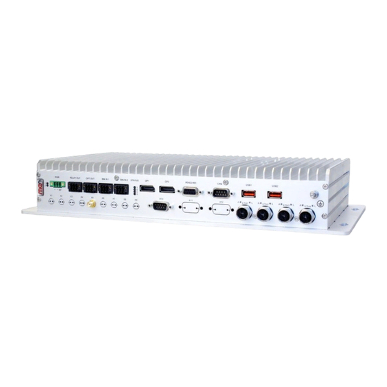
Product Overview Product Architecture 1.2.1 Interfaces Figure 1. Front interfaces Photocoupler Serial Interface 5 Serial Interface 3 USB 2.0 outputs (COM4: IBIS Slave) (COM2: RS422/485) Relay outputs Binary (digital) DisplayPort Earthing stud inputs Power Status LEDs Status LEDs (Ethernet) RELAY OUT OPT OUT BIN IN 1 BIN IN 2... -
Page 15: Figure 3. Board Layout (Pcbs Inside The System)
Product Overview Figure 3. Board layout (PCBs inside the system) BL51E Shu le Board SC31 SC31 SD card ETH4 J/P1 J/P1 slot ETH3 ETH2 ETH1 2.5“ SATA HDD/SSD 2x USB shu le Mezzanine slots (Legacy Serial I/O) Slot C RS422/485... -
Page 16: Functions
Product Overview 1.2.2 Functions Figure 4. Functional diagram ECC DDR3 eMMC SDRAM Card 2 micro-SIM Slots USB 2.0 2 Antennas PCIe Mini PCIe DisplayPort 1.2 Card Slot 2 micro-SIM DisplayPort 1.2 Slots USB 2.0 PCIe Mini 2 Antennas HD Audio out PCIe Card Slot USB 2.0... -
Page 17: Technical Data
Product Overview Technical Data The following CPU types are supported: Intel Atom x5-E3930, 2 cores, 2 threads, 1.3 GHz, 1.8 GHz Turbo Boost, 6.5 W, 2 MB cache Intel Atom x5-E3940, 4 cores, 4 threads, 1.6 GHz, 1.8 GHz Turbo Boost, 9.5 W, 2 MB cache Intel Atom x7-E3950, 4 cores, 4 threads, 1.6 GHz, 2.0 GHz Turbo Boost, 12 W, 2 MB cache... - Page 18 Product Overview SD/microSD card slot 1 × SD card; UHS-I (104 MB/s (SDR104)); externally accessible Video 2 × DisplayPort 1.2 Audio 1 × D-Sub, 9-pin, plug S/PDIF output Stereo line input, single-ended Stereo line output, differential 2 ×...
- Page 19 Mechanical Specifications Dimensions: (W) 390 mm, (D) 215 mm, (H) 66 mm See the MEN website for technical product drawings including the exact dimensions of BL51E: www.men.de/products/bl51e/#doc Weight: 4.25 kg approx., 5.5 kg approx. (box PC in 19" insertion frame) ...
- Page 20 Supported kernel: 4.8 or higher. For older kernels (e.g., 4.4.x), patches for the Intel Atom Processor E3900 Series platform are also available. Driver support Windows Windows 10 IoT Enterprise 64-bit See the MEN website for available packages and more details on supported functions: www.men.de/products/bl51e/#downl 20BL51E00 E2 2020-03-27 Page 20...
-
Page 21: Cooling Concept
Product Identification MEN documentation may describe several different models and design revisions of the BL51E. You can find the article number, design revision and serial number affixed to the BL51E. Article number: Indicates the product family and model. This is also MEN’s main ... -
Page 22: Getting Started
Getting Started Getting Started Unpacking the BL51E After unpacking, check whether there are any transport or other damages on the system. If one of the following situations arises, have the equipment checked by service personnel: The power cable or plug is damaged. -
Page 23: Configuring The Hardware
Getting Started Configuring the Hardware Check your hardware requirements before mounting the BL51E. Modifications are difficult or impossible to do when the BL51E is mounted. MEN offers suitable accessory articles for BL51E. See the MEN website for ordering information: www.men.de/products/bl51e/#ord 2.2.1... -
Page 24: Installing An Hdd/Ssd
Getting Started 2.2.2 Installing an HDD/SSD The following steps are necessary: » If there is already an HDD/SSD in the device, make sure that there are no write or read processes on the disk. » To remove the HDD/SSD shuttle, pull the front handle on the shuttle 90° to the left. »... -
Page 25: Installing In-System Devices
See the MEN website for ordering information: www.men.de/products/bl51e/#ord Opening the BL51E and installing optional components may lead to a loss of the certification and therefore make the declaration of conformity invalid. If you install components with wireless functionality other guidelines or standards regarding wireless functionality might be applicable (e.g., R&TTE Guideline of the EU). -
Page 26: Mounting The Bl51E
Getting Started Mounting the BL51E 2.3.1 Safety Instructions for Mounting Risk of Damages or Injuries Make sure that the cabinet or the wall where you want to install the system supports the weight of the system. Risk of Fire Through Overheating Make sure that the equipment does not overheat. -
Page 27: Mounting On A Wall Or A Horizontal Surface
5 mm » Place the BL51E so that the wide openings of the mounting holes are over the screw heads (1). » Slide the box down so that the screw heads slip into the narrow part of the mount- ing hole (2). -
Page 28: Installing The Bl51E In A 19" Rack
Getting Started 2.3.3 Installing the BL51E in a 19" Rack MEN offers a mounting kit which makes it possible to install the BL51E in a 19" rack. See the MEN website for ordering information: www.men.de/products/bl51e/#ord » Remove the bottom panel of the BL51E. - Page 29 Getting Started » Install the two heats sinks supplied with the kit at the sides of the BL51E using four M2.5x12 TX8 Torx screws for each heat sink. The screws are included in the delivery of the kit. » Insert the box PC into the opening in the kit’s front panel.
- Page 30 » Screw the BL51E onto the kit’s bottom plate using the screws removed before. » Fix the BL51E at the kit’s front panel using the M3x10 TX10 Torx screws delivered with the kit. Apply thread locker to the screws. »...
-
Page 31: Connecting And Starting
Connecting and Starting 2.4.1 Safety Instructions for Connection Adhere to the following safety instructions before you connect the BL51E: Works on the computer system may only be carried out by personnel qualified for the specific task, who, based on their training and experience, are able to identify risks and avoid potential hazards when working with these products/systems. -
Page 32: Connecting An Earthing Cable
Connect a USB keyboard and mouse to the USB connectors at the front panel. » Connect a flat-panel display capable of displaying the resolution of 2560 x 1600 to a DisplayPort connector at the front panel of the BL51E. » Connect all other peripheral devices needed for your system function. -
Page 33: Connecting The Power Supply
» Now you can make configurations in the UEFI firmware. 2.4.6 Configuring the UEFI Firmware for PXE Boot To enable PXE booting of the BL51E, configure the UEFI firmware as follows: For UEFI mode: Menu MEN: Setup Mode [Extended] Menu Advanced: Network Stack Configuration >... -
Page 34: Installing Operating System Software
MDIS System Package The BL51E is supported by the MDIS framework. MDIS stands for MEN Driver Interface System and is a framework for device drivers for almost any kind of I/O hardware. It greatly simplifies system configuration, also in combination with specialized board BSPs. -
Page 35: Using The Bl51E Under Windows
LM63 temperature and fan controller Note: Not all MEN products provide the devices above. Therefore, not all MDIS5 devices may be available in your system. Note: The device name suffix number (e.g., _1, _2) is assigned during the driver installa- tion. -
Page 36: Managing Rtc Time Adjustments
The ERTC time will not be updated and is out of date. During the next system boot, the OS would use the outdated time. MEN provides a dedicated ERTC driver to manage system time adjustments. See the MEN website for user manual Windows ERTC/SMB Support Package. -
Page 37: Configuring Wireless Functions
Getting Started 2.8.3 Configuring Wireless Functions You can configure the following by accessing a configuration register on the SMBus: Enable/disable power for a wireless interface card Switch SIM card allocation to wireless interface cards The smb2_ctrl tool included in the Windows ERTC/SMB Support Package (13Y021-70) gives easy access to SMBus/I2C registers. -
Page 38: Using The Bl51E Under Linux
2.9.1 Accessing SMBus/I2C Devices using MEN Tools MEN provides a number of MDIS software tools for accessing BL51E functions via the SMBus, which are included in the MDIS5 System Package for Linux,13MD05-90: xm01bc_ctrl provides access to the board management controller (BMC) ... - Page 39 RESET_IN mode get hardware variant ID exit QM-Mode (for production tests only) (c) 2008 by MEN mikro elektronik GmbH » For example, if you want to look up the voltage values, use the following command: sudo xm01bc_ctrl -v xm01bc_1...
-
Page 40: Accessing Smbus/I2C Devices Using Standard Linux I2C Tools
MEN CPUs under Linux. 2.9.4 Setting the UART Modes of BL51E Interfaces MEN provides a Linux tool that allows to switch the UART modes of legacy serial I/O interfaces. See the MEN website for more information and documentation: www.men.de/software/13sc24-91/ The Linux tool supports the following BL51E interfaces (front panel designations): ... -
Page 41: Configuring Wireless Functions
The following examples assume that the SMBus number is 1. Disable the power for a wireless interface card: This disables wireless interface card A of the BL51E. - You need to read the current value before writing, so you can change only the desired bit. -
Page 42: Switching Serial Interfaces
Getting Started 2.9.6 Switching Serial Interfaces The GPIO controller instance 1 is used to activate or switch serial interfaces of the box PCs from UART to digital I/O. The functions are switched via multiplexers. The default device name of the instance 1 of the GPIO controller 16z034_GPIO is "gpio_2". -
Page 43: Functional Description
Functional Description Functional Description Power Supply The BL51E is supplied via a power inlet connector at the front panel. Table 5. Connector types – power supply (3-pin COMBICON) Connector Type On BL51E 3-pin COMBICON plug, e.g., Phoenix Contact 1843800 MC 1,5/ 3-GF-3,5 Mating 3-pin COMBICON receptacle, e.g., Phoenix Contact 1863314 MCVR 1,5/ 3-... -
Page 44: Ignition
Functional Description 3.1.1 Ignition You can use the ignition pin to control the start-up and shut-down of the BL51E without having to disconnect the power supply. To use the ignition function, connect pin IGNITIONCON (KL15) to the power input pin POWERCON_IN (KL30) via a switch or a controller. -
Page 45: Figure 9. Ignition And Shut-Down Delay Watchdog State Diagram
Table 64, SMB Register (0x4E) on page If the ignition watchdog is running and the timer is not restarted, the BL51E is forced into power down mode after approximately 5 minutes. Figure 9. Ignition and shut-down delay watchdog state diagram... -
Page 46: Cpu
100-ms steps from 100 ms up to 1:49:10 (hh:mm:ss) - 65536 steps. 3.3.2 Temperature Measurement The BL51E uses a temperature device to measure the local CPU board temperature. The temperature device is connected to the BMC via I2C, and is supported by the firmware. 20BL51E00 E2... -
Page 47: Status Leds
Functional Description 3.3.3 Status LEDs Table 8. Status LEDs at front panel Appearance Label Color Function Yellow Power LED On: Power supply active Yellow CPU Board status LED Chapter 3.3.3.1 CPU Board Status LED on page 48 Yellow User LED Off: Default state ... -
Page 48: Real-Time Clock (Rtc)
Real-Time Clock (RTC) The BL51E includes a real-time clock connected to the processor as the system RTC (ERTC) RX-8571. The RTC has an accuracy of approximately 1.7 seconds/day (11 minutes/ year) at 25°C. The real-time clock device is connected to the CPU via SMBus. -
Page 49: Trusted Platform Module (Tpm)
Functional Description Trusted Platform Module (TPM) A trusted platform module for authenticating the hardware to ensure platform integrity is available on the BL51E. The TPM module is compliant to the TPM v2.0 specification. Memory 3.6.1 System RAM The DRAM system memory of BL51E is scalable. -
Page 50: Emmc
3.7.3 eMMC An eMMC multimedia card is connected to the eMMC interface of the CPU. This is a hardware option, and the BL51E will come with an eMMC device already soldered on the board, with the capacity ordered. 20BL51E00 E2... -
Page 51: Isolation Voltages
Functional Description Isolation Voltages The isolation voltages are defined as follows: Table 12. Group Number Signal Interface Remaining Groups AC Voltage Power Groups 2 - 10 1500 Groups 1, 3 - 10 Shield Audio RS232 ETH1 (X-Coded) Groups 1 - 2, 4 - 10 ETH2 (X-Coded) Groups 1 - 3, 5 - 10 ETH3 (X-Coded) -
Page 52: Video
Functional Description Video The BL51E supports: DisplayPort interfaces on two DisplayPort 1.2a connectors 3.9.1 Front Connection Table 13. Connector types – DisplayPort Connector Type On BL51E 20-pin DisplayPort receptacle Mating 20-pin DisplayPort plug Table 14. Pin assignment – DisplayPort... -
Page 53: Front Interface Adapters
Functional Description 3.9.2 Front Interface Adapters Many third-party suppliers offer adapters from DisplayPort to other graphics interfaces. The maximum resolution depends on the adapter used. Supported interfaces include: HDMI Single-link DVI Dual-link DVI It depends on the operating system, driver software and use case if an active or passive DisplayPort adapter is applicable. -
Page 54: Audio
Functional Description 3.10 Audio The BL51E supports: HD Audio 3.10.1 Front Connection Table 16. Connector types – 9-pin D-Sub plug Connector Type On BL51E 9-pin D-Sub plug according to DIN41652/MIL-C-24308, with thread bolt UNC 4-40 Mating 9-pin D-Sub receptacle according to DIN41652/MIL-C-24308 Table 17. -
Page 55: Usb
Functional Description 3.11 The BL51E supports: xHCI implementation 3.11.1 Front Connection Table 19. Connector types – USB 2.0 Connector Type On BL51E 4-pin USB Type A receptacle according to Universal Serial Bus Specification Revision 1.0 Mating 4-pin USB Type A plug according to Universal Serial Bus Specification Revision 1.0... -
Page 56: Ethernet
3.12.1 Front Connection Table 22. Connector types – Ethernet (8-pin M12 X-coded) Connector Type On BL51E 8-pin M12 receptacle, X-coded e.g., Phoenix Contact SACC-CI-M12FS-8CON-L180-10G - 1402457 Mating 8-pin M12 plug, X-coded e.g., Phoenix Contact VS-08-M12MS-10G-P SCO - 1417430 (straight) e.g., Phoenix Contact VS-08-M12MR-10G-P SCO - 1417443 (angled) Table 23. -
Page 57: Ethernet Status Leds
Functional Description 3.12.2 Ethernet Status LEDs Figure 1, Front interfaces on page 14 for the position of the LEDs. Table 26. Ethernet status LEDs Appearance Label Color Function Yellow Indicates Ethernet activity On: n/a USB1 Off: No activity Blinking: Transmit/Receive activity ... -
Page 58: Wireless Functionality
Functional Description 3.13 Wireless Functionality 3.13.1 PCI Express Mini Card The BL51E supports: Full-Mini cards according to the PCI Express Mini Card Standard Figure 3, Board layout (PCBs inside the system) on page 15 for the position of ... - Page 59 Functional Description Table 29. Pin assignment – PCI Express Mini Card connector (USB 2.0) WAKE# +3.3V COEX1 COEX2 1.5V CLKREQ# UIM_PWR UIM_DATA REFCLK- UIM_CLK REFCLK+ UIM_RST UIM_VPP Mechanical key UIM_IC_DM UIM_IC_DP W_DISABLE1# PERST# PERn0 +3.3Vaux PERp0 +1.5V SMB_CLK PETn0 SMB_DATA PETp0 USB_D- USB_D+...
-
Page 60: Sim Card
To get access to a mobile phone network you need a SIM card (subscriber identity module) and a contract with a mobile service provider. Please note that MEN does not provide mobile services or SIM cards! 3.13.3 Antenna Connectors (Optional) -
Page 61: Relay Outputs
Functional Description 3.14 Relay Outputs The relay outputs of the BL51E have the following characteristics: Switching current: Input voltage 0 V DC to 30 V DC: 2 A max. Input voltage 30 V DC to 50.4 V DC: 0.9 A max. -
Page 62: Photocoupler Outputs
Functional Description 3.15 Photocoupler Outputs The photocoupler outputs of the BL51E have the following characteristics: Default state (Shutters): Open Switching voltage: 50.4 V DC max. Current (switching and continuous): 120 mA max. 3.15.1 Front Connection Table 34. -
Page 63: Digital I/O
Functional Description 3.16 Digital I/O The BL51E supports: Input voltage range: 0 V DC to 50.4 V DC External reference voltage V_REF (for definition logical high and low level): 20 V DC to 50.4 V DC Switching voltage threshold: ... - Page 64 Functional Description Table 41. Signal mnemonics – digital inputs Signal Direction Function DIG_IN_x Digital input lines Table 42. Signal mnemonics – reference voltage on digital inputs Signal Direction Function DIG_IN_VREF+ Reference voltage for digital inputs DIG_IN_VREF- Reference common ground for digital inputs 20BL51E00 E2 2020-03-27 Page 64...
-
Page 65: Ibis
3.17 IBIS IBIS (Integrated On-Board Information System) is a serial interface, which has been established as a standard in the transportation sector for the controlling of display modules. The BL51E supports: IBIS slave interface Data rate: up to 19.2 kbit/s 3.17.1... -
Page 66: Odometer Input
5 V DC to 50.4 V DC Pulse counter frequency: 2 kHz max. The pulse counter value is read inside the FPGA in the BL51E by IP core 16Z082_IMPULSE. See the MEN website for downloads and documentation: https://www.men.de/products/16z082_impulse 3.18.1 Front Connection Table 46. -
Page 67: Gnss
Functional Description 3.19 GNSS The BL51E supports: Sensor: TELIT SL869 (32 channel GNSS architecture) Antenna type: Active Passive Standard: NMEA RTCM 104 GLONASS FDMA Galileo Accuracy: approx. 1.5 m A-GPS Time-to-first-fix (cold start): < 35 s ... -
Page 68: Rs232
Functional Description 3.20 RS232 The BL51E supports: Data rate: up to 115.2 kbit/s 60-byte transmit buffer 60-byte receive buffer Handshake lines: CTS/RTS Usable as serial console 3.20.1 Rear Connection Table 49. Connector types – 9-pin D-Sub plug... -
Page 69: Rs422/Rs485
Functional Description 3.21 RS422/RS485 The BL51E supports: Data rate: up to 1 Mbit/s Software configurable as full-duplex or half-duplex Note: The data lines are not equipped with termination resistors. 3.21.1 Front Connection Table 52. Connector types – 9-pin D-Sub receptacle... -
Page 70: Can Bus
Functional Description 3.22 CAN Bus The BL51E supports: Data rate: up to 1 Mbit/s 3.22.1 Front Connection Table 56. Connector types – 9-pin D-Sub plug Connector Type On BL51E 9-pin D-Sub plug according to DIN41652/MIL-C-24308, with thread bolt UNC 4-40... -
Page 71: Legacy Serial I/O
Functional Description 3.23 Legacy Serial I/O The BL51E supports: Two configurable serial interfaces at the front of the BL51E using MEN standard SA- Adapters Serial interface 1 (X11) supports: RS232, RS422/RS485, digital I/O or IBIS functionality For using the 08SA15-00 SA-Adapter with digital I/O functionality at serial interface 1 (X11) you have to change a setting in the FPGA to switch from UART to digital I/O. -
Page 72: Uefi Firmware
The mode can be switched under the MEN tab. Chapter 4.3.2 MEN Menu on page When accessing the BL51E via a serial console only the <Esc> key can be used. 20BL51E00 E2 2020-03-27 Page 72 ... -
Page 73: Main Menu
UEFI Firmware 4.3.1 Main Menu In the Main menu you can look up system parameters and set system language, date and time. Aptio Setup Utility - Copyright (C) 2017 American Megatrends, Inc. Main Advanced Chipset Security Boot Save & Exit /----------------------------------------------------+-------------------------\ BIOS Information ^|Choose the system... -
Page 74: Men Menu
UEFI Firmware 4.3.2 MEN Menu The MEN menu has been adapted in order to simplify access to important functions. You can find information regarding board name, board revision and serial number as well as several sub-menus. Aptio Setup Utility - Copyright (C) 2017 American Megatrends, Inc. - Page 75 Setup Mode Standard Extended 4.3.2.2 MEN Menu – Sub-Menu BMC Settings In the sub-menu BMC Settings you can find board information that is read out via the Board Management Controller (BMC), as well as the following sub-functions: Table 60. Sub-menu BMC Settings...
- Page 76 UEFI Firmware 4.3.2.3 MEN Menu – Sub-Menu Network Settings In the sub-menu Network Settings you can activate and deactivate the Ethernet controllers and the PXE boot functionality. Table 61. Sub-Menu Network Settings Sub-menu Function Options MEN Network Settings Gigabit Ethernet ETH1/ETH2...
-
Page 77: Advanced Menu
UEFI Firmware 4.3.3 Advanced Menu In the Advanced menu you can change configurations regarding Console Redirection, CPU, Network Stack, CSM, SDIO Configuration and Trusted Platform Memory. Aptio Setup Utility - Copyright (C) 2017 American Megatrends, Inc. Main Advanced Chipset Security Boot Save &... -
Page 78: Chipset
UEFI Firmware 4.3.4 Chipset Most of the functions in this menu normally do not have to be changed during operation. If necessary, by entering the configuration menu you can change the settings regarding, e.g, HD-Audio or PCI Express. Aptio Setup Utility - Copyright (C) 2017 American Megatrends, Inc. Main Advanced Chipset... -
Page 79: Security Menu
UEFI Firmware 4.3.5 Security Menu In the Security menu you can enter passwords for the user profiles User and Administrator. Aptio Setup Utility - Copyright (C) 2017 American Megatrends, Inc. Main Advanced Chipset Security Boot Save & Exit /----------------------------------------------------+-------------------------\ Password Description |Set Setup Administrator |Password If ONLY the Administrator's password is set,... - Page 80 UEFI Firmware Table 66. Security modes Setting Description No password is set Booting the system and opening the UEFI setup is not protected. Only administrator password Booting the system is not protected. is set For opening the UEFI setup, the administrator password is required.
-
Page 81: Boot Menu
UEFI Firmware 4.3.6 Boot Menu In the boot menu you can make settings regarding boot behavior and boot order. Aptio Setup Utility - Copyright (C) 2017 American Megatrends, Inc. Main Advanced Chipset Security Boot Save & Exit /----------------------------------------------------+-------------------------\ Boot Configuration |Number of seconds to Setup Prompt Timeout |wait for setup... -
Page 82: Save And Exit Menu
UEFI Firmware 4.3.7 Save and Exit Menu In the Save and Exit menu you can set how to handle changes made within the setup and exit the setup. Using the Boot Override function you can boot from a medium different from the one set in the boot order. -
Page 83: Hardware/Software Interface
Hardware/Software Interface Hardware/Software Interface This chapter is intended for software developers or board integrators who need deeper knowledge of the implementation details of the BL51E interfaces and its internal connections. SMBus/I2C Devices Table 67. SMBus/I2C devices 8-Bit Address 7-Bit Address... -
Page 84: Bl51E Information Eeprom
If you use standard I2C commands under Linux, use 7-bit addresses. 5.1.1 BL51E Information EEPROM The following table provides the internal byte structure of the BL51E information EEPROM at address 0xAC/0x56. Table 68. SMBus/I2C – Board information EEPROM – address map... -
Page 85: Smbus Configuration Registers
Hardware/Software Interface Bit Field Description 15:9 Year Year since 1990 in binary format. This allows a range from 1990 to 2117. Month Month in binary format (1 to 12) Day of month in binary format (1 to 31) Note: If the word has value , the date field has not been programmed. - Page 86 Hardware/Software Interface 5.1.2.2 SIM Card, PCIe MiniCard Power Signals SMB Register (0x42) Table 72. SMB Register (0x42) MINI_A MINI_B MINI_C MINI_D Name SIMA_SW SIMB_SW SIMC_SW SIMD_SW _PWR_EN _PWR_EN _PWR_EN _PWR_EN Access Reset Bit Field Description SIMx_SW Switch between primary and secondary SIM card of the PCIe Mini Card 0: Secondary SIM connected to the PCIe Mini Card ...
- Page 87 Hardware/Software Interface 5.1.2.3 Odometer, Photocoupler, Relay Signals SMB Register (0x44) Table 73. SMB Register (0x44) ODO_PU_ OPT_EN OPT_EN REL_EN REL_EN Name _PD150K _PD75K Access Reset Bit Field Description ODO_PU_EN Enable pull-up resistor of the odometer interface 0: Pull-up resistor active ...
- Page 88 Hardware/Software Interface Table 75. Odometer default / reset states Sink ODO_PD75K ODO_PD150K ODO_PU_EN EN/DIS During Reset Last value Last value Last value Last value After Reset Last value Last value Last value Last value During power cycle After power cycle 20BL51E00 E2 2020-03-27 Page 88...
-
Page 89: Fpga Ip Core Implementation
Hardware/Software Interface 5.1.2.4 Digital Input SMB Register (0x4E) Table 76. SMB Register (0x4E) WDOG Name DIG_IN[7] DIG_IN[6] DIG_IN[5] DIG_IN[4] DIG_IN[3] DIG_IN[2] DIG_IN[1] Access Reset Bit Field Description DIG_IN[7:1] Value of the connected isolated input 0: Input active 1: Input inactive ... -
Page 90: Bmc Api (Application Programming Interface)
Hardware/Software Interface BMC API (Application Programming Interface) The BL51E uses a generic command interface for communication between the host (CPU) and the controller (BMC). Application software uses command packets to communicate with the BMC. The application software controls the BMC via I2C/SMBus. The device address is 0x4D (in 7-bit, non-shifted notation) or 0x9A/0x9B (in 8-bit, shifted notation, write/read). - Page 91 Hardware/Software Interface The packet types are directly mapped to the corresponding SMBus “bus protocols” as defined in the System Management Bus Specification. Table 79. API – Packet types mapping on SMBus Packet Type SMBus Protocol PT_SB Send byte PT_RBD Read byte PT_WBD Write byte PT_RWD...
- Page 92 Hardware/Software Interface Commands WDOG_TIME_SET and WDOG_TIME_GET Command WDOG_TIME_SET Opcode: 0x14 Packet Type: PT_WWD Data 0 WD_TOUT (LSB) Data 1 WD_TOUT (MSB) Command WDOG_TIME_GET Opcode: 0x14 Packet Type: PT_RWD Data 0 WD_TOUT (LSB) Data 1 WD_TOUT (MSB) Bit Field Description WD_TOUT Trigger timeout, in steps of 100 ms 0x0001: 100 ms ...
- Page 93 5.3.1.3 Power Resume Mode Commands These commands allow configuring the behavior of the BL51E in case the power is reapplied after a power failure and input voltages return to their allowed limits. The setting is persistent, i.e. it is stored in non-volatile memory.
- Page 94 Hardware/Software Interface Commands RESUME_MODE_SET and RESUME_MODE_GET Command RESUME_MODE_SET Opcode: 0x20 Packet Type: PT_WBD Data RES_MODE Command RESUME_MODE_GET Opcode: 0x20 Packet Type: PT_RBD Data RES_MODE Bit Field Description RES_MODE Resume mode 0x00: Off 0x01: On 0x02: Former 20BL51E00 E2 2020-03-27 Page 94 ...
- Page 95 5.3.1.4 Reset Signal Blocking These commands allow blocking of BL51E reset inputs. The setting is persistent, i.e. it is stored in non-volatile memory. In a system with master and slave CPU boards, normally the slave boards will get a reset whenever the master board resets.
- Page 96 Hardware/Software Interface 5.3.1.5 Software Reset These commands allow performing CPU resets under application software control. Different types of resets are available: SW_RESET issues a “warm reset”. SW_COLD_RESET issues a “cold reset”. SW_RTC_RESET issues a “cold reset”, together with an RTC reset. ...
- Page 97 Hardware/Software Interface 5.3.1.6 Power Button These commands allow initiating power button events. Table 85. BMC API – Power button commands Command Packet Type Opcode Functional Description PWRBTN PT_WBD Perform pressing of power button 0x33 PWRBTN_OVRD PT_WBD Perform power button override, i.e. 0x34 assert the power button for more than 4 seconds to initiate system shutdown...
- Page 98 Hardware/Software Interface 5.3.1.7 Voltage Supervision The voltage supervision commands allow the customer application to monitor different voltages on the BL51E. Table 86. BMC API – Voltage supervision commands Command Packet Type Opcode Functional Description VOLT_LOW(0) PT_RWD Get lower limit of +3.3 V (in mV)
- Page 99 Hardware/Software Interface Command VOLT_ACT(x) Opcode: 0x60 + x Packet Type: PT_RWD Data 0 Actual value of voltage x (LSB) Data 1 Actual value of voltage x (MSB) Command NUM_VOLTS Opcode: 0x8E Packet Type: PT_RBD Data Number of supervised voltages 20BL51E00 E2 2020-03-27 Page 99 ...
- Page 100 Hardware/Software Interface 5.3.1.8 Error Counters The error counter commands allow querying and clearing error counters. The BMC provides error counters for each type of error that can occur. Using this information, the application software can determine how often certain errors have occurred, but it is not possible to determine the chronological order of the errors.
- Page 101 Hardware/Software Interface Command ERRCNT_xx (16 to 32) Opcode: 0xB0 + x Packet Type: PT_RBD Data Value of error counter number xx Command ERR_CNT_CLR This command clears all error counters. Opcode: 0x7F Packet Type: PT_WBD Data 0x69 Command NUM_ERR_CNTRS Opcode: 0x8D Packet Type: PT_RBD Data Number of error counters...
- Page 102 Hardware/Software Interface 5.3.1.9 Firmware Revision The firmware revision commands allow querying the separate parts of the BMC firmware revision. Table 89. BMC API – Firmware version commands Command Packet Type Opcode Functional Description GETREV_WORD0 PT_RWD Get firmware revision major part 0x80 GETREV_WORD1 PT_RWD...
- Page 103 5.3.1.10 Hardware Board Type This command allows the BMC to query the board type, i.e. a unique ID that MEN assigns to each hardware board the generic BMC is implemented on. The board type is programmed into the BMC during production. The setting is persistent, i.e. is stored in a non-volatile memory.
- Page 104 Hardware/Software Interface 5.3.1.11 Last Error This command allows querying the last error. Table 90. BMC API – Last error command Command Packet Type Opcode Functional Description ERR_LAST PT_RBD Get last error 0x90 Command ERR_LAST Opcode: 0x90 Packet Type: PT_RBD Data LAST_ERR_CODE Bit Field Description...
- Page 105 Hardware/Software Interface 5.3.1.12 Power Failure Flags This command allows querying the power failure flags of the BL51E. Table 91. BMC API – Power failure flags command Command Packet Type Opcode Functional Description ERR_PWR_FLAGS PT_RBD Get power failure flags 0x91 Command ERR_PWR_FLAGS Whenever a power failure occurs, the respective flag is set to 1 until the Power Failure Flag Register is cleared.
- Page 106 Hardware/Software Interface 5.3.1.13 Reset Reason This command allows querying the reason of the last reset. The BMC maintains a Reset Reason Register that stores the reason for the last reset issued by the BMC. Table 92. BMC API – Reset reason command Command Packet Type Opcode...
- Page 107 Hardware/Software Interface 5.3.1.14 Clear Error Registers This command allows clearing the Reset Reason Register, Last Error Register and Power Failure Flag Register, collectively called ’error registers’. Table 93. BMC API – Clear error registers command Command Packet Type Opcode Functional Description ERR_REG_CLR PT_WBD Clear error registers...
- Page 108 Hardware/Software Interface 5.3.1.16 Operating Hours Counter This command allows querying the operating hours counter. The operating hours counter counts the number of hours and minutes the board has been (at least partly) powered on, i.e. when the system is in S3 or S0 state. S0 to S5 are the power states as defined in the ACPI specification, or an equivalent state.
- Page 109 Hardware/Software Interface 5.3.1.17 Status LED Control This command allows controlling status LEDs, depending on implementation on the product. Table 96. BMC API – Status LED control command Command Packet Type Opcode Functional Description LED_CTRL_SET PT_WBD Set LED state 0xA0 LED_CTRL_GET PT_RBD Get LED state 0xA0...
-
Page 110: Maintenance
The power pin of the power inlet connector is protected by a fuse. Fuses are not intended to be exchanged by the customer. Your warranty for the BL51E will cease if you exchange fuses on your own. Please send the product to MEN for repair if a fuse blows.
Need help?
Do you have a question about the BL51E and is the answer not in the manual?
Questions and answers