Table of Contents
Advertisement
Installation, Operating and Service Instructions for
FORCEVFO
Models:
• FORCEVFO-3-075E
• FORCEVFO-3-100E
• FORCEVFO-4-120E
• FORCEVFO-4-150E
• FORCEVFO-5-175E
• FORCEVFO-5-190E
Manual Contents
1. Dimensional Description, Specification &
Dimensional Data . . . . . . . . . . . . . . . . . . . . . 4
2. Pre-installation . . . . . . . . . . . . . . . . . . . . . . . 8
3. Packaged Boiler Assembly . . . . . . . . . . . . 10
4. Water Boiler Piping & Trim . . . . . . . . . . . . . 11
6. Venting . . . . . . . . . . . . . . . . . . . . . . . . . . . . 17
7. Electrical . . . . . . . . . . . . . . . . . . . . . . . . . . . 20
8. Oil Piping . . . . . . . . . . . . . . . . . . . . . . . . . . . 23
9. System Start-Up . . . . . . . . . . . . . . . . . . . . . 25
10. Operating . . . . . . . . . . . . . . . . . . . . . . . . . . 28
11. Maintenance & Service . . . . . . . . . . . . . . . 34
12. Boiler Cleaning . . . . . . . . . . . . . . . . . . . . . 36
13. Troubleshooting . . . . . . . . . . . . . . . . . . . . . 38
14. Service Parts . . . . . . . . . . . . . . . . . . . . . . . 40
15. Burner Specifications . . . . . . . . . . . . . . . . 46
Appendix . . . . . . . . . . . . . . . . . . . . . . . . . . 47
TO THE INSTALLER:
Affix these instructions adjacent to boiler.
TO THE CONSUMER:
Retain these instructions for future reference.
For service or repairs to boiler, call your heating contractor. When seeking information on boiler, provide
Boiler Model Number and Serial Number as shown on Rating Label.
110547-01 - 4/20
• FORCEVFOT-3-075E
• FORCEVFOT-3-100E
• FORCEVFOT-4-120E
• FORCEVFOT-4-150E
• FORCEVFOT-5-175E
• FORCEVFOT-5-190E
Page
TM
Residential Water
9700609
As an ENERGY STAR Partner, U.S. Boiler Company
has determined that the FORCEVFO-3-075E,
FORCEVFOT-3-075E, FORCEVFO-4-120E, and
FORCEVFOT-4-120E meets the ENERGY STAR®
guidelines for energy efficiency established by the
United States Environmental Protection Agency
(EPA)."
• Water Boiler
• Natural Draft
• Oil-Fired
Advertisement
Table of Contents

Related Manuals for ProSelect FORCEVFO Series

Summary of Contents for ProSelect FORCEVFO Series
-
Page 1: Table Of Contents
Installation, Operating and Service Instructions for FORCEVFO • Water Boiler • Natural Draft • Oil-Fired Residential Water Models: • FORCEVFO-3-075E • FORCEVFOT-3-075E • FORCEVFO-3-100E • FORCEVFOT-3-100E • FORCEVFO-4-120E • FORCEVFOT-4-120E • FORCEVFO-4-150E • FORCEVFOT-4-150E • FORCEVFO-5-175E • FORCEVFOT-5-175E • FORCEVFO-5-190E •... - Page 2 FORCEVFO Installation & Service Manual IMPORTANT INFORMATION - READ CAREFULLY All boilers must be installed in accordance with National, State and Local Plumbing, Heating and Electrical Codes and the regulations of the serving utilities. These Codes and Regulations may differ from this instruction manual. Authorities having jurisdiction should be consulted before installations are made.
- Page 3 FORCEVFO Installation & Service Manual DANGER DO NOT store or use gasoline or other flammable vapors or liquids in the vicinity of this or any other appliance. WARNING Improper installation, adjustment, alteration, service or maintenance can cause property damage, personal injury or loss of life.
-
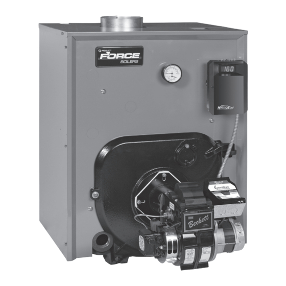
Page 4: Dimensional Data
Be sure to tighten swing door fastener completely when service is completed. Product Description, Specification and Dimensional Data The FORCEVFO Series boiler is a cast iron oil-fired water boiler designed for closed forced circulation heating systems. This boiler must be vented by... - Page 5 FORCEVFO Installation & Service Manual Product Description, Specification and Dimensional Data (continued) Table 1A: Dimensional Data Dimensions Recommended Minimum Chimney Approx. Boiler Series Water Content Rectangle "A" "B" "C" Round in Dia. Height ft. Gallons in. x in. FORCEVFO-3 17-3/8" 8-1/4"...
- Page 6 FORCEVFO Installation & Service Manual Product Description, Specification and Dimensional Data (continued) 110547-01 - 4/20...
- Page 7 FORCEVFO Installation & Service Manual Product Description, Specification and Dimensional Data (continued) 110547-01 - 4/20...
-
Page 8: Pre-Installation
ANSI/NFPA 31 National Standard ANSI/NFPA 31, Installation standard. of Oil Burning Equipment. 2. FORCEVFO Series boilers can be installed in rooms with clearances from combustible material as listed above. Listed clearances cannot be reduced for alcove or closet installations. - Page 9 FORCEVFO Installation & Service Manual Pre-Installation (continued) Direct communication with outdoors. NOTICE Clearance to venting is for single wall Minimum free area of 1 square inch vent pipe. If Type L vent is used, clearance may per 4,000 BTU per hour input of all be reduced to the minimum required by the vent equipment in space.
-
Page 10: Packaged Boiler Assembly
FORCEVFO Installation & Service Manual Packaged Boiler Assembly A. REMOVE CRATE. E. INSTALL OIL BURNER. 1. Remove all fasteners at crate skid. 1. Open burner carton and remove contents. Refer to Table 15-1. 2. Lift outside container and remove all other inside protective spacers and bracing. -
Page 11: Water Boiler Piping & Trim
FORCEVFO Installation & Service Manual Water Boiler Piping and Trim 1. If this boiler is used in connection with NOTICE Failure to pipe boiler as specified in this refrigeration systems, the boiler must be manual may result in excessive system noise, installed so that the chilled medium is piped water line fluctuations and water carry over. - Page 12 FORCEVFO Installation & Service Manual Water Boiler Piping and Trim (continued) To perform a long term pressure test including the boiler, ALL trapped air must first be removed from the boiler. A loss of pressure during such a test, with no visible water leakage, is an indication that the boiler contained trapped air.
- Page 13 FORCEVFO Installation & Service Manual Water Boiler Piping and Trim (continued) 110547-01 - 4/20...
- Page 14 FORCEVFO Installation & Service Manual Water Boiler Piping and Trim (continued) 110547-01 - 4/20...
-
Page 15: Tankless & Indirect Water Heater Piping
FORCEVFO Installation & Service Manual Tankless and Indirect Water Heater Piping 3. FLUSHING OF HEATER — All water A. CONNECT TANKLESS HEATER PIPING as contains some sediment which settles on the shown in Figure 5-1. See Table 5-2 for Tankless inside of the coil. - Page 16 FORCEVFO Installation & Service Manual Tankless and Indirect Water Heater Piping (continued) Figure 5-1: Schematic Tankless Heater Piping Table 5-2: Tankless Heater Data Boiler Rating Pressure Model (Gal/Min) Drop (PSI) FORCEVFO-3-075 3.00 FORCEVFO-3-100 3.25 FORCEVFO-4-120 3.75 FORCEVFO-4-150 4.00 FORCEVFO-5-175 4.25 FORCEVFO-5-190 4.75 110547-01 - 4/20...
-
Page 17: Venting
FORCEVFO Installation & Service Manual Venting WARNING Vent this boiler according to these instructions. Failure to do so may cause products of combustion to enter the home resulting in severe property damage, personal injury or death. • Insufficient Combustion Air Supply may result in the production and release of deadly carbon monoxide (CO) into the home which can cause severe personal injury or death. - Page 18 FORCEVFO Installation & Service Manual Venting (continued) Figure 6-1: Recommended Vent Pipe Arrangement and Chimney Requirements Figure 6-2: Proper and Improper Locations of Draft Regulator 110547-01 - 4/20...
- Page 19 FORCEVFO Installation & Service Manual Venting (continued) 2. Minimum Draft Overfire – The draft induced by a d. Clean Chimney – Chimney shall be free of all chimney must create at least a pressure of -0.02 loose debris. inches water column (“ w.c.). The pressure at 5.
-
Page 20: Electrical
FORCEVFO Installation & Service Manual Electrical 7. Wiring should conform to Figures 7-1 through DANGER 7-2. Positively assure all electrical connections are B. INSTALL A ROOM THERMOSTAT on an inside unpowered before attempting installation or wall about four feet above floor. Never install service of electrical components or connections thermostat on an outside wall or where it will be of the boiler or building. - Page 21 FORCEVFO Installation & Service Manual Electrical (continued) 110547-01 - 4/20...
- Page 22 FORCEVFO Installation & Service Manual Electrical (continued) 110547-01 - 4/20...
-
Page 23: Oil Piping
FORCEVFO Installation & Service Manual Oil Piping A. GENERAL WARNING Under no circumstances can copper with sweat 1. Use flexible oil line(s) so the burner swing door style connectors be used. can be opened without disconnecting the oil supply piping. NOTICE Some jurisdictions require the use of a 2. - Page 24 FORCEVFO Installation & Service Manual Oil Piping (continued) C. TWO PIPE OIL LINES Table 8-3: Single-Stage Units (3450 RPM) - Two Pipe Systems 1. For two piped systems, where more lift is required, the two-stage fuel unit is Maximum Length of Tubing recommended.
-
Page 25: System Start-Up
FORCEVFO Installation & Service Manual System Start-Up WARNING All boilers equipped with burner swing door have a potential hazard which can cause severe property damage, personal injury or loss of life if ignored. Before opening swing door, turn off service switch to boiler to prevent accidental firing of burner outside the combustion chamber. - Page 26 FORCEVFO Installation & Service Manual System Start-Up (continued) 4. ADJUST DRAFT REGULATOR for a draft of 3. CHECKOUT -0.02" (water gauge) over the fire after chimney Put the system into operation and observe has reached operating temperature and while at least once complete cycle to make sure burner is running.
- Page 27 FORCEVFO Installation & Service Manual System Start-Up (continued) e. Check operating control on boiler 2. IF NOZZLE CONTINUES TO DRIP, repeat applications equipped with tankless Paragraph H, No. 1 above. If this does not heater(s). With burner off, draw hot water stop the dripping, remove cut-off valve and until burner starts, then turn off hot water seat, and wipe both with a clean cloth until...
-
Page 28: Operating
FORCEVFO Installation & Service Manual Operating A. HydroStat 3250 PLUS SEQUENCE OF If the heating system is unable to supply needed heat to the house, OPERATION the ECONOMY Dial should be turned IMPORTANT This boiler is equipped with lower setting (example: In a three zone a feature that saves energy by reducing the house, turn the dial to 2 or 1.) Conversely, boiler water temperature as the heating load... - Page 29 FORCEVFO Installation & Service Manual Operating (continued) Degrees Fahrenheit or Celsius: The Circulator Activation Options control has the ability to operate in When in the default mode, the HydroStat degrees Fahrenheit or Celsius. When activates the circulator (C1/C2 contacts) on operating in Celsius, a c will appear in calls to TT.
- Page 30 FORCEVFO Installation & Service Manual Operating (continued) To change the well type • Turn the LO TEMP dial to access the Program Mode - indicated in the display as Pro. • Turn the HI TEMP dial to select feature 8. •...
- Page 31 FORCEVFO Installation & Service Manual Operating (continued) Default Dial Setting Feature Options Description Setting Purge Inactive Thermal Pre-Pruge Purge Active Degrees Fahrenheit Fahrenheit or Celsius Degree Celcius LWCO Manual or Automatic Reset Automatic Reset Manual Reset Circulator operation on TT call only Circulator Options Circulator operation on ZC/ZR call only Circulator operation on call from either...
- Page 32 FORCEVFO Installation & Service Manual Operating (continued) LWCO TEST LCO WARNING The red Low Water light should illuminate and the Allow the boiler to fully cool before adding water. burner circuit (B1 and B2) should de-energize. NOTE: The control must be installed with a Hydrolevel e.
- Page 33 FORCEVFO Installation & Service Manual Operating (continued) Important Product Safety Information: Refractory Ceramic Fiber Product WARNING Some boiler components contain refractory ceramic fibers (RCF). RCF has been classified as a possible human carcinogen. When exposed to temperatures above 1805°F, such as during direct flame contact, RCF changes into crystalline silica, a known carcinogen.
-
Page 34: Maintenance & Service
FORCEVFO Installation & Service Manual Maintenance and Service Instructions i. Apply a moderate amount of good quality A. MAINTENANCE OF LOW WATER CUT-OFF DEVICES pipe dope to the pipe threads on the probe, leaving the two end threads bare. DO NOT WARNING use PTFE (Teflon) tape. - Page 35 FORCEVFO Installation & Service Manual Maintenance and Service Instructions (continued) A leaky system will increase the volume of ix. Continue to circulate the water for a few make-up water supplied to the boiler which can hours. significantly shorten the life of the boiler. Entrained x.
-
Page 36: Boiler Cleaning
FORCEVFO Installation & Service Manual Boiler Cleaning WARNING All boiler cleaning must be completed with burner service switch turned off. Boilers equipped with burner swing door have a potential hazard which can cause severe property damage, personal injury or loss of life if ignored. - Page 37 FORCEVFO Installation & Service Manual Boiler Cleaning (continued) Figure 12-1: Cleaning of Boiler Flueways WARNING The boiler must be connected to an approved chimney in good condition. Serious property damage could result if the boiler is connected to a dirty or inadequate chimney. The interior of the chimney flue must be inspected and cleaned before the start of the heating season and should be inspected periodically throughout the heating season for any obstructions.
-
Page 38: Troubleshooting
FORCEVFO Installation & Service Manual Troubleshooting A. COMBUSTION 5. DIRT — A fuel filter is a good investment. Accidental accumulation of dirt in the fuel 1. NOZZLES — Although the nozzle is a system can clog the nozzle or nozzle strainer relatively inexpensive device, its function is and produce a poor spray pattern from the critical to the successful operation of the oil... - Page 39 FORCEVFO Installation & Service Manual Troubleshooting (continued) 11. SHUT DOWN NOISE — If the flame runs out Note: The Safety Monitoring Circuit (SMC) is of air before it runs out of fuel, an after burn designed to provide lockout in the event with noise may occur.
- Page 40 FORCEVFO Installation & Service Manual THIS PAGE IS INTENTIONALLY LEFT BLANK. 110547-01 - 4/20...
-
Page 41: Service Parts
FORCEVFO Installation & Service Manual Service Parts All FORCEVFO™ Series Boiler Service Parts may be obtained through your local Ferguson branch. 110547-01 - 4/20... - Page 42 FORCEVFO Installation & Service Manual Service Parts (continued) 110547-01 - 4/20...
- Page 43 FORCEVFO Installation & Service Manual Service Parts (continued) Item Part Description FORCEVFO-3 FORCEVFO-4 FORCEVFO-5 Number 110552-03 Block Assembly 110552-04 Rear Heater for Water Includes: Complete Block 110552-05 Assembly, Target 110553-03 Wall Insulation, Coil Gasket, Coil Cover Non Heater 110553-04 Plate/Hardware 110553-05 110554-03 Canopy Includes: Canopy, Canopy Gasket...
- Page 44 FORCEVFO Installation & Service Manual Service Parts (continued) 110547-01 - 4/20...
- Page 45 FORCEVFO Installation & Service Manual Service Parts (continued) Item Part Description FORCEVFO-3 FORCEVFO-4 FORCEVFO-5 Number 110573-03 Complete Jacket Carton for Water, Rear 110573-04 Heater 110573-05 110571-03 Complete Jacket Carton for Water, Non- 110571-04 Heater 110571-05 Temperature & Pressure Gauge, 1/4" NPT x 109966-01 2-1/2"...
- Page 46 FORCEVFO Installation & Service Manual Service Parts (continued) Item No. Description Part Number FORCEVFO-3 FORCEVFO-4 FORCEVFO-5 110498-03 Beckett 110499-04 110500-05 Honeywell Shown 103880-01 R7284P1080 Primary Control Beckett GeniSys Obtain 7505P1515 Locally 110547-01 - 4/20...
-
Page 47: Burner Specifications
FORCEVFO Installation & Service Manual Burner Specifications Table 15-1: Beckett Settings Firing Burner Pump Boiler Model Rate Nozzle Shipped Head Model Pressure (Setting) Shutter Band FORCEVFO-3-075 0.75 0.65 X 60B (Hago) Installed FORCEVFO-3-100 1.00 0.85 x 60B (Hago) Field Provided FORCEVFO-4-120 1.20 1.00 x 60B (Hago) Installed... -
Page 48: Appendix
FORCEVFO Installation & Service Manual Appendix - Aftermarket Low Water Cut Off (LWCO) WARNING DO NOT ATTEMPT to cut factory wires to install an aftermarket Low Water Cut Off (LWCO). Only use connections specifically identified for Low Water Cut Off. In all cases, follow the Low Water Cut Off (LWCO) manufacturer's instructions. - Page 49 FORCEVFO Installation & Service Manual Appendix - Aftermarket Low Water Cut Off (LWCO) How to Test A 24 VAC LWCO is used primarily for gas fired Shut off fuel supply. Lower water level until water boilers where a 24 volt control circuit exists within level is BELOW the LWCO.
- Page 50 FORCEVFO Installation & Service Manual SERVICE RECORD DATE SERVICE PERFORMED 110547-01 - 4/20...
- Page 51 FORCEVFO Installation & Service Manual SERVICE RECORD DATE SERVICE PERFORMED 110547-01 - 4/20...
- Page 52 FORCEVFO Installation & Service Manual SERVICE RECORD DATE SERVICE PERFORMED 110547-01 - 4/20...