Table of Contents
Advertisement
Advertisement
Table of Contents

Summary of Contents for VKB T-Rudder
- Page 1 Rudder Pedals T Rudder Installation and setup manual Version 1.1 от 20.05.2014...
- Page 2 ©2014 VKB. All rights reserved. ©2014 Written by Victorus. All rights reserved.
-
Page 3: Table Of Contents
Content Introduction ........... . 3 Pedals installation . -
Page 5: Introduction
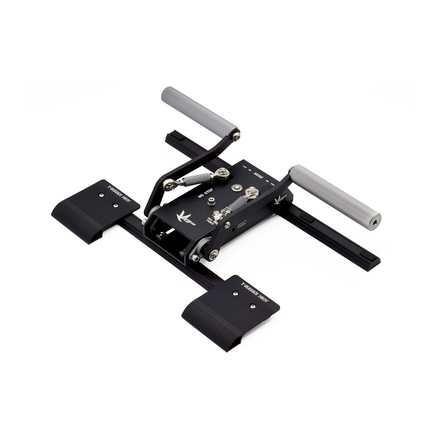
Introduction T Rudder pedals let the virtual pilot to control the rudder just like a real pilot. This device has not onboard controller and must be connected to the one of the following devices: Cobra Z joystick, ▼ Tiny Box external controller, ▼... -
Page 6: Order Of Assembly
T Rudder pedals. Installation and setup manual Табл. 1.1. Номер Наименование Примечание Back legs Foreleg Support shaft Syncronizer False panel Case Force lever Shaped nut with screw Foot bearing UTP cable Velcro strip For fixation on the pile surfaces. Silicon legs For installation on the firm and smooth surfaces. - Page 7 Fig. 2.3. 3. Prepare back legs for foot bearing installation: 3.1. insert two shaped nuts into internal housing of the leg, M5 nut closer to end cap, M4 one closer to the center. 3.2. drive a M4 screw into the nut to fix them both in an extreme position (fig. 2.4). 2.4.
- Page 8 T Rudder pedals. Installation and setup manual The back leg is attached to the case by two screws. Three adjustment holes make possible to set the angle between the case and the leg thus providing pedal setup for pilot foot size. The screw, drived into the fourth hole, is using as an axis. Before the leg is fixed in a chosen position you can rotate it around this screw.
- Page 9 Fig. 2.8. 4.5. Screw the back legs to a case using М5х25 screw with spring washer. Drive the screws into threaded rivet nuts of the axis holes from the external side of the case (fig. 2.9). 2.9. screw Fig. 2.9. 4.6.
- Page 10 T Rudder pedals. Installation and setup manual Fig. 2.10. 4.8. Install false panel to its place. 5. Install foreleg. 5.1. Drive screws with washers out of shaped nuts (fig. 2.11). 2.11. Fig. 2.11. 5.2. Insert unscrewed screws into the holes of the case (fig. 2.12). 2.12.
- Page 11 Fig. 2.13. 5.4. Align the leg and the forward case side centers (fig. 2.14) 2.14. Fig. 2.14. 5.5. Tighten the screws. 6. Install foot bearings. 6.1. Unfix the M4 screw so you can move shaped nuts along the leg freely. 6.2.
- Page 12 T Rudder pedals. Installation and setup manual 6.3. Choose one of the notches on the side edge of the foot bearing in a correspondense of your foot size and thus the distance between fot bearing and the support shaft (fig. 2.16). 2.16.
-
Page 13: Support Shaft Height Setup
Support shaft height setup General info Usability of pedals is provided by support shaft height. You must rotate sincronizers to set up this height. The height of both shafts in neutral rudder position must be the same. Order of setup To set up support shaft height, execute the following operations. -
Page 14: Pedals Connection
сonfiguration program. Use this link http://ftp.vkb sim.pro/Programms/ to download this program. This manual describes only few opportunities of this program. Detailed description you can find in VKB NJoy32 controller configurator User manual. Use link http:// ftp.vkb sim.pro/Documentations/ to download file controller.pdf (Only Russian language now). -
Page 15: Axis Type
Axis type MARS sensor is a digital device. You must properly set its type. Activate Physical Axes tab (fig. 2.1). 2.1. Fig. 2.1. Choose D_MaRS value from Input combobox. This choise corresponds to digital MARS sensor. Check AC (Autocalibration) option. It allows automatic calibration of the pedals with every connection. -
Page 16: Axis Parameters Setup
T Rudder pedals. Installation and setup manual If when the pedal is in extreme position but marker is not on range limit, it is recommended to increase the support shaft height (see“Support shaft height setup” on page 11). If it is impossible, set Mpl value equal to 10. Axis parameters setup Set deadzones of the pedal axis using DzLo field (deadzone in the center) and DzHi field (deadzones on range limits). -
Page 17: Variants Of Pedals Steadiness Support
Variants of pedals steadiness support Rubber end caps of the legs provide pedals steadiness on most kinds of surfaces. If you want to have aditional steadiness on firm and smooth surfaces, such as parquet, laminated flooring board, marble etc., you can use included self adhesive silicon legs. - Page 18 T Rudder pedals. Installation and setup manual...
Need help?
Do you have a question about the T-Rudder and is the answer not in the manual?
Questions and answers