
Related Manuals for Emec LOTUS MAXI

Summary of Contents for Emec LOTUS MAXI
- Page 1 Read this manual completely before you start with the installation and start-up. Do not discard this manual and store it nearby the generator for later use. English...
- Page 3 Directory General Safety Guidelines Storage and Transport Construction Installation First Startup „LOTUS“ - Controller „Click-Wheel“ Configuration Menu LOTUS Terminal board Failure Messages...
- Page 4 General Safety Guidelines General remarks • • Notice: • • Symbols in the manual Warning: Caution! Notice or advice: Symbols at the installation site Warning: Danger! Prohibition!
- Page 5 Safety chapter The three basic rules: Correct and proper use: • • • • • • • • • • • • • •...
- Page 6 Qualification of personnel: Warning! Activity Qualification level Technical expert: Qualified personnel: Instructed personnel: Customer service department: Personal protective equipment...
- Page 7 Safety information: Warning! Danger from incorrect operation • • Warning! Danger due to toxic and explosive ClO • Instructions for entering • a room where a chlorine dioxide system is installed • • Notes You got into contact with acid: for the system operator •...
- Page 8 • The LOTUS system was supplied with concentrated chemicals but the dosing pumps have not yet started: Directions for the operator • • • • • EU Declaration of Conformity • • • • • • • Notice:...
- Page 9 Storage and Transport Safety information: Warning! • • Notice: Danger of material damage • • • Packaging: Ambient conditions: Data Value...
- Page 10 Construction General description • • WARNING: follow European directive DIN EU 939 concerning HYDROCHLORIC ACID follow European directive DIN EU 938 concerning SODIUM CHLORITE...
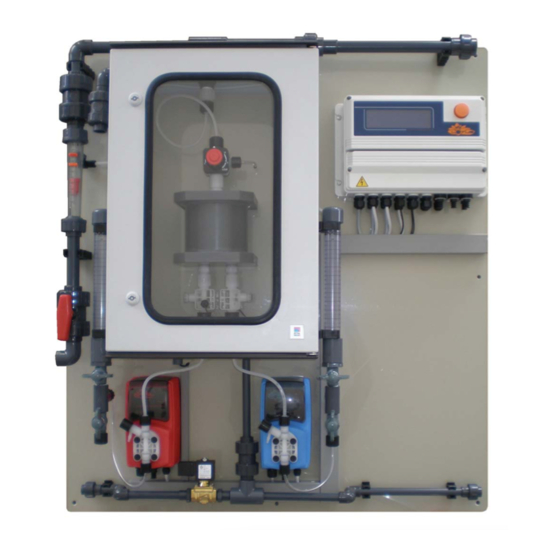
- Page 11 System overview HCl 9% NaClO 7,5%...
- Page 12 Reactor overview...
- Page 13 Installation Safety information: Warning! • • • • • • • • General requirements for the installation site Notice: • • • • • • • • • • • General requirements for the plant installation Notice: • • • •...
- Page 14 Requirements for the water Safety information: Warning! Serious malfunctions at the plant or corrosion damages in the pipe-work of the treated water should be possible in case the following requirements to the water – the chlorine dioxide is produced for – as well as for the dilu- tion water are not fulfilled: •...
- Page 15 Hydraulic Installation Safety information: Warning! Warning against illegal operation Danger! Warning of toxic chlorine dioxide vapour • • • • Warning! The reactor can explode Main components: • • • • • • • •...
- Page 16 Chlorine Dioxide Generator LOTUS D 4.5.1 Installation example A • Point of injection (34) direct in the main water supply. • Operation mode: “Proportional” Fig. 4.1 Reactor outlet valve Main water supply Flushing unit with vacuum relieve valve Water meter (frequency or analog signal) Acid tank in safety tub Bypass line Chlorite tank in safety tub...
- Page 17 Chlorine Dioxide Generator LOTUS D 4.5.2 Installation example B • The reactor outlet valve (9) of the LOTUS system is located beneath the point of injection (34). • Operation mode: “Proportional” h > 0 Fig. 4.2 Reactor outlet valve Main water supply Flushing unit with vacuum relieve valve Water meter (frequency or analog signal) Acid tank in safety tub...
- Page 18 Chlorine Dioxide Generator LOTUS D 4.5.3 Installation example C • The reactor outlet valve (9) of the LOTUS system is located beneath the point of injection (34). • Operation mode: “Proportional” h < 0 Fig. 4.3 Reactor outlet valve Main water supply Flushing unit with vacuum relieve valve Water meter (frequency or analog signal) Acid tank in safety tub...
- Page 19 Chlorine Dioxide Generator LOTUS D 4.5.4 Installation example D • Batch tank filling with water supply module • Operation mode: “Batch” Fig. 4.4 Flushing unit with vacuum relieve valve Batch or storage tank Acid tank in safety tub Back pressure valve Chlorite tank in safety tub Module “Water Supply”...
- Page 20 Hydraulic Installation of accessories and options 4.6.1 Bypass line Safety information: Danger! Warning of toxic chlorine dioxide vapour • • • • Warning! The reactor can explode • • Function: 4.6.2 Safety equipment bypass line Safety information: Warning! The reactor can explode Risk of explosion in the bypass line Function:...
- Page 21 4.6.3 Flushing unit with vacuum relieve valve Safety information: Warning! Degassing ClO solution can still vaporize in the bypass line. Danger! Poisonous ClO solution can escape Function:...
- Page 22 4.6.4 Back pressure valve Function: 4.6.5 Flow generator for bypass line Function: • •...
- Page 23 4.6.6 Module “Ventilation unit” Function: • • • • Installation: • • • 4.6.7 Module “Water supply” Function: • • • • • • •...
- Page 24 4.6.8 Suction lances Safety information: Danger! Warning of toxic chlorine dioxide gas Warning! Warning of corrosive acid or toxic chlorite solution Assembly: Caution! The suction hoses must not be plugged into the chemical tanks yet! Caution!
- Page 25 Electrical Installation Caution! • • • • • • • • • • • 4.7.1 Power supply Caution! • • • 4.7.2 Installation of an emergency stop switch Warning! • • •...
- Page 26 4.7.6 Installation of a gas detector Notice: Placing of warning labels Danger! Toxic substances Chlorine dioxide Access only for authorized personnel! Prohibition! No Fire, naked light and smoking Sodium Chlorite NaClO...
- Page 27 11. Ordering Information...
- Page 28 Startup Warning! For the first startup it is strongly recommended to use water instead of the chemicals to avoid accidents with hazardous chem.s because of leakages! So in the following explanations the water is called Preparations • “6. LOTUS Controller” “Click-Wheel”...
- Page 29 • “Stop” • “Status” “Check” “Status” • “Priming” • “ESC” Caution! •...
- Page 30 „LOTUS“ Controller Start display LOTUS Main display LOTUS “Click-Wheel”...
- Page 31 Control element „Click-Wheel“ „Click-Wheel“ • „Yes“ • „No“...
- Page 32 Status Display LOTUS “Status” “Check” „Pump“ „Check“ ON/OFF STAND-BY “Stand-by” “Stand-by” PRIMING < >...
- Page 33 Logbook LOTUS “Logbook” “ESC”...
- Page 34 Configuration Menu LOTUS * * * * Caution! • • „7.7 System Settings“ Sub-menues:...
- Page 35 Pumps – Calibration of dosing pumps • • Calibration: “Priming” “Pumps” “Start” “Strokes” “ml” “Water”...
- Page 36 Sensors – Calibration of the chlorine dioxide probe and temperature sensor „Proportional & Measuring“...
- Page 37 Contact water meter • • • „Water Meter“ “Water Meter” Dimension: “Value” „Imp./Ltr.“ „Ltr./Imp.“ Value: Max. Value: Resolution: Notice: “Analog” Timeout: “Timeout” “0” “OVERFLOW”...
- Page 38 Analog outputs “Analog Outputs”...
- Page 39 Operation mode “Operation Mode” Proportional: Constant: “Stand-by” Batch: Analog: Notice: “Analog” Prop. & Reading: Notice: “Prop. & Reading”...
- Page 40 7.5.1 Proportional mode Prod. Capacity: Warning: • “Prod. Capacity” • • “Prod. Capacity” General Notices: But for very low water flows, resp. water consumption it can be dangerous to do this and should be absolutely avoided! “Overflow” LOTUS Overflow...
- Page 41 7.5.2 Constant mode “Stand-by” “Stand-by” Capacity 1: “Batch tank empty” Capacity 2: “Stand-by” Situation STAND-BY (44, 45) MD DI (5,6) “STAND-BY” Notice: “Capacity 1” 7.5.3 Analog mode Capacity at 20 mA: Notice: “Stand- by” Notice: “Analog”...
- Page 42 7.5.4 Batch mode “Batch tank empty” “Stand-by” MD DI MD DI Level tank Level Situation Step Terminal Terminal empty tank full 1, 2 Notice: “Tank empty/full” Step 1: Step 2: Step 3: Step 4:...
- Page 43 Failure Level-switch: LOTUS 7.5.5 Prop. & Reading mode Set-Point: Limit value: Notice: “Prop.& Reading”...
- Page 44 System settings Dos-Check: “0” Pass-Code 2: the main menu Default value: “0 9 1 6”. Caution! Write the new passcode down in your documents or into the „Test Certificate” (appen- dix A) for later using! Notice: “Reset” “0 9 1 6” Pass-Code 1: Default value: “0 0 0 0”.
- Page 45 LOTUS Terminal board...
- Page 46 8. LOTUS Terminal board To set the proximity switch enter into configuration menu and select Probe Flow Alarm Flow contact can be enabled to stop a dosing procedure using a N.O. contact mode (normally open) or N.C. contact mode (normally clo- sed) when status on blocks changes.
- Page 47 Configuration Menu Summary PUMP CALIBRATION SENSORS WATER METER ANALOG OUTPUT mA INPUT BYPASS ALARM PROBE FLOW ALARM...
- Page 48 Inputs: Block, Terminal Function Electrical data Outputs: Block, Terminal Function Electrical data...
- Page 49 10. Failure messages “RESTART” Message Problem Solution Leave the room immediately and shut the door! Shut down the plant with emergency There is a massive leakage inside stop switch. Reactor Leakage the reactor housing (3). Wear complete personal protective equipment. Take attention to chapter “1.4 Safety Chapter”...
- Page 50 Message Problem Solution Notice: “Restart”...
- Page 51 COMMUNICATION (TCP/IP & GPRS) This instrument can be controlled and programed remotely using the system called ERMES and a standard web browser (i.e.: Google Chrome or Safari). In order to use this service an internet connection is required (lan or wan) and user must configure the instrument to obtain a valid IP address (through a valid DHCP service or manually).
- Page 52 COMMUNICATION (MESSAGES Setup - RS485) This instrument can send emails and / or sms when a system failure or warning happens. If instrument is configured to operate through the LAN only email messages can be send. Otherwise if instruments has a mobile modem both SMS and emails messages can be send.
- Page 53 COMMUNICATION (LOG & LOGBOOK and time. Note: To view on instrument’s display the archived logs select LOGBOOK...
- Page 54 Enter the website and, after registration, set plants. EMEC instruments with ETHERNET or GSM/GPRS Configuration will be immediatly connected and available for remote control. Furthermore, with ERMES you can receive alarm messages via email, with different report option on instrument status.
- Page 55 Problem Possible solution Check best signal coverage for operator choice. Modem is compatible with the following GSM frequencies: 900 -1800 -1900 MHz (three-band). Not compatible with 3G only operators. SIM type is: What to do before to install the SIM into instru- ment’s modem Mini-SIM (classica SIM card in uso nei telefoni) Lenght 25 (mm) - Width 15 (mm) - thickness 0,76 (mm)
- Page 56 MODBUS WARNING...
- Page 61 Read this manual completely before you start with the installation and start-up. Do not discard this manual and store it nearby the generator for later use. English R1-10-12...
- Page 62 R1-10-12...
- Page 63 Directory General Safety Guidelines Storage and Transport Construction Installation 5…… Manual Part 2: Startup and Operation … LOTUS Terminal board Technical Data R1-10-12...
- Page 64 General Safety Guidelines General remarks • • Notice: • • Symbols in the manual Warning: Caution! Notice or advice: Symbols at the installation site Warning: Danger! Prohibition! R1-10-12...
- Page 65 Safety chapter The three basic rules: Correct and proper use: • • • • • • • • • • • • • • R1-10-12...
- Page 66 Qualification of personnel: Warning! Activity Qualification level Technical expert: Qualified personnel: Instructed personnel: Customer service department: Personal protective equipment R1-10-12...
- Page 67 Safety information: Warning! Danger from incorrect operation • • Warning! Danger due to toxic and explosive ClO • Instructions for entering • a room where a chlorine dioxide system is installed • • Notes You got into contact with acid: for the system operator •...
- Page 68 • The LOTUS system was supplied with concentrated chemicals but the dosing pumps have not yet started: Directions for the operator • • • • • EU Declaration of Conformity • • • • • • • Notice: R1-10-12...
- Page 69 Storage and Transport Safety information: Warning! • • Notice: Danger of material damage • • • Packaging: Ambient conditions: Data Value R1-10-12...
- Page 70 Construction General description • • R1-10-12...
- Page 71 System overview HCl 9% NaClO 7,5% R1-10-12...
- Page 72 Reactor overview R1-10-12...
- Page 73 Installation Safety information: Warning! • • • • • • • • General requirements for the installation site Notice: • • • • • • • • • • • General requirements for the plant installation Notice: • • • •...
- Page 74 Requirements for the water Safety information: Warning! Serious malfunctions at the plant or corrosion damages in the pipe-work of the treated water should be possible in case the following requirements to the water – the chlorine dioxide is produced for – as well as for the dilu- tion water are not fulfilled: •...
- Page 75 Hydraulic Installation Safety information: Warning! Warning against illegal operation Danger! Warning of toxic chlorine dioxide vapour • • • • Warning! The reactor can explode Main components: • • • • • • • • R1-10-12...
- Page 76 4.5.1 Installation example A • • R1-10-12...
- Page 77 4.5.2 Installation example B • • h > 0 R1-10-12...
- Page 78 4.5.3 Installation example C • • h < 0 R1-10-12...
- Page 79 4.5.4 Installation example D • • R1-10-12...
- Page 80 Hydraulic Installation of accessories and options 4.6.1 Bypass line Safety information: Danger! Warning of toxic chlorine dioxide vapour • • • • Warning! The reactor can explode • • Function: 4.6.2 Safety equipment bypass line Safety information: Warning! The reactor can explode Risk of explosion in the bypass line Function: R1-10-12...
- Page 81 4.6.3 Flushing unit with vacuum relieve valve Safety information: Warning! Degassing ClO solution can still vaporize in the bypass line. Danger! Poisonous ClO solution can escape 4.6.4 Back pressure valve Function: 4.6.5 Flow generator for bypass line Function: • • R1-10-12...
- Page 82 4.6.6 Module “Ventilation unit” Function: • • • • Installation: • • • 4.6.7 Module “Water supply” Function: • • • • • • • • R1-10-12...
- Page 83 4.6.8 Suction lances Safety information: Danger! Warning of toxic chlorine dioxide gas Warning! Warning of corrosive acid or toxic chlorite solution Assembly: Caution! The suction hoses must not be plugged into the chemical tanks yet! Caution! R1-10-12...
- Page 84 Electrical Installation Caution! • • • • • • • • • • 4.7.1 Power supply Caution! • • • 4.7.2 Installation of an emergency stop switch Warning! • • • R1-10-12...
- Page 85 4.7.3 Connection of the bypass pump Caution! 4.7.4 Installation of a gas detector (accessory) Notice: Placing of warning labels Danger! Toxic substances Chlorine dioxide Access only for authorized personnel! Prohibition! No Fire, naked light and smoking Sodium Chlorite NaClO R1-10-12...
- Page 87 10. Technical Data R1-10-12...
- Page 88 R1-10-12...
Need help?
Do you have a question about the LOTUS MAXI and is the answer not in the manual?
Questions and answers