Table of Contents
Advertisement
Quick Links
Advertisement
Table of Contents

Related Manuals for Laird WL3004


Summary of Contents for Laird WL3004
- Page 1 WL3004 Liquid to Air Cooling System Specification and User Manual Version 1.2...
- Page 2 Laird. All specifications are subject to change without notice. Laird assumes no responsibility and disclaims all liability for losses or damages resulting from use of or reliance on this information. All Laird products are sold subject to the Laird Terms and Conditions of sale (including Laird’s limited warranty) in effect from time to time, a copy of which will be furnished upon request.
-
Page 3: Table Of Contents
Table of Contents Revision History ............................ 5 About this Manual ......................... 6 Terms of Guarantee ..........................6 Contact Information ..........................7 Product Identification ........................8 Unit Specifications ..........................8 Identification Plate ..........................8 Safety Regulations ........................9 Hazard classes ............................ 9 Safety Symbols ........................... - Page 4 Re-packaging of the unit ........................32 Storing the Unit ..........................32 Disposal............................. 32 Disposal of Operating Materials ......................32 Return of the unit to Laird Thermal Systems ..................32 Wear Parts and Spare Parts ....................33 Addendum............................35 Flow scheme ............................. 35...
-
Page 5: Revision History
Revision History DATE DESCRIPTION NAME Page 04/22/20 Document template updated to LTS format, spelling errors Maria corrected. Mjalgard 03/22/19 Set point of temperature switch changed from 55°C to Jonathan 45°C. Knutsson 07/31/19 Henrik Olsson... -
Page 6: About This Manual
Terms of Guarantee General sale and delivery terms of LAIRD apply. The buyer accepts these terms, at the latest when signing the contract of purchase. The particular terms of guarantee and duration of guarantee of the unit in question can be taken from the contract documents as well as from the order confirmation. -
Page 7: Contact Information
Your name and address Name of contact at your address Product data as on identification plate: Type of unit, serial number and year of manufacture Company contact: Laird Thermal Systems Prumyslová 497 462 11 Liberec Czech Republic... -
Page 8: Product Identification
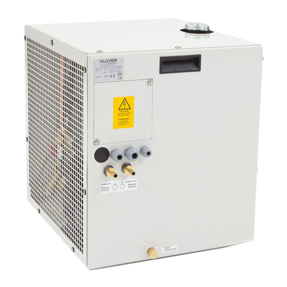
2. Product Identification Unit Specifications Manufacturer Laird Thermal Systems GmbH Type of product Water-air cooler Type of unit WL 3004 Article number 387002779 Unit specifications Identification Plate The identification plate is attached to the front side of the unit (see Fig. 1). -
Page 9: Safety Regulations
2. Safety Regulations Hazard classes In this document safety instructions are using standardized representation and symbols. Depending on the probability of their incidence and the severances of consequences three hazard classes are used DANGER Reference to direct danger for humans. Inobservance will lead to irreversible injuries or exitus. -
Page 10: Hints For Safe Operation
Hints for Safe Operation NOTE Conduct inspections on a regular time base! This will ensure that the appropriate measures will be carried out indeed. The unit is operational save. It was built according to the existing state of technology. Despite this the unit could cause hazards if it is used in a way it was not intended for ... -
Page 11: Environmental Issues
Environmental Issues Environmentally conscious and anticipatory behavior of staff avoids environmentally hazardous impacts. The following principles apply for environmentally conscious behavior: Environmentally hazardous substances must not get into the ground or the drains. They should be kept in appropriate containers. Environmentally hazardous substances must be fed to utilization or disposal according to ... -
Page 12: Guards
Guards Direct access to hazardous parts or areas of the unit is restricted by the unit cover. The cover may only be removed for the purpose of maintenance or repair works and shall be replaced prior to taking the unit back into operation. The unit cover is fixed by 8 screws. The left-side panel can be removed independently from the main cover by opening 7 quarter-turn fasteners. -
Page 13: In Case Of Accidents
In Case of Accidents Should you or another person be injured when working with the unit: Stay calm! Render first aid! Call the company first-aider without exception! ... -
Page 14: Product Description
The manufacturer is not liable for damage occurring when using the unit in a way it was not intended for. When using the unit in a way it was not intended for, the manufacturer’s warranty given by Laird Thermal Systems will expire. -
Page 15: Unit Components
Unit Components Additional information can be retrieved from the flow scheme shown in the addendum. The unit consists of the following main components: Fig. 6: Main components 1 Coolant container and heat exchanger 2 Cooling circuit 3 Casing Cooling Circuit In the cooling circuit the coolant is driven by the pump to the device that is to be cooled and back via the return flow. -
Page 16: Specifications
Specifications Dimensions and weight Length: 444 mm (w/o hose nipples) Width: 398 mm Height: 481 mm Weight: 38.5 kg (empty) Coolant capacity: 3.7 liters Dimensions and weight Performance data Cooling capacity: 3.0 kW Throughput: > 6.0 lpm at 6.0 bars Mains voltage: 230 VAC, 50/60 Hz Current draw:... -
Page 17: Setting-Up Requirements
Setting-up Requirements Installation Location The location must be even. When choosing the installation location, the following must be kept in mind: the air flow of the cooling air must not be restricted, forward and back flow connections must be easily accessible and all tubes must be installed without sharp bends. -
Page 18: Transport
Lift the unit with a forklift or jack lift off the transportable pallet. Dispose of the packaging material in accordance with regional regulations. NOTE Laird Thermal Systems advises to keep the transportable pallet for later transportation of the unit. -
Page 19: Initial Operation
6. Initial Operation Safety Indications Related to Initial Operation CAUTION Danger of malfunction caused by faulty connections during initial operation! Before switching on the unit make sure that all safety equipment of the unit is implemented and functional all connections were properly made ... - Page 20 Cooling Circuit Connection and Filling CAUTION Risk of damage by using improper cooling hoses! This may lead to damage to persons, damage to the unit or corrosion damage. When choosing cooling hoses pay attention to sufficient burst strength and compatibility with ...
-
Page 21: Electrical Connections
Open the coolant container by removing the cap. Fill the coolant container with about 3.7 liters of water or water/glycol mixture. Close the coolant container by fitting the cap. Electrical Connections DANGER Danger to life through electrical shock when working on the electrical equipment of the unit! Switch off the unit before starting your work! ... -
Page 22: Daily Start-Up
Remove the access plate after unscrewing the 2 screws. Feed the mains cable through one of the cable bushings and make the connection to the terminal. Then do the same with the wires for the implementation of the safety circuit. Remount the access plate. -
Page 23: Controlling The Unit
7. Controlling the Unit The unit is controlled using the controls of the equipment that is to be cooled. All alarm and error signaling is only indicated on the control panel of the equipment that is to be cooled. Safety Indications for Controlling the Unit CAUTION Lack of coolant may destroy the pump! Operate the unit only when the filling of coolant container is sufficient! -
Page 24: Settings
By-pass valve The by-pass valve is set by the manufacturer to a maximum pressure of 8 bars. If any modification to this setting should be required, please contact the Laird Thermal Systems service department to receive briefing. Setting the Thermostat Fig. - Page 25 The unit is delivered by the manufacturer with the thermal switch being set to 55°C. The thermal switch can be adapted to meet changing needs. Increase the temperature setpoint Turn the knob clockwise. The switch-off temperature is set to a higher value. ...
-
Page 26: Disruptions
More help can be found in the following paragraph. In case you do not succeed in identifying the problem cause by means of this manual please contact the service department of Laird Thermal Systems. Trouble Shooting For trouble shooting you may rely on the following: Alarm signaling within the safety circuit of the device to be cooled ... -
Page 27: Maintenance And Cleaning
9. Maintenance and Cleaning Diligent maintenance is the prime factor for assuring an error-free and efficient operation of the unit. Operating personnel can perform these tasks when properly trained. Maintenance Schedule Device Activity Interval Criteria Tools Performer Heat Exchanger Clean Minimum weekly Plate fins and Slotted screw... -
Page 28: Cleaning Of Strainer
Cleaning of Strainer Fig. 12: Locations of ball valve and strainer 1 Strainer cover 2 Ball valve Disconnect the unit from mains. Remove the side panel. Close the ball valve. CAUTION A small amount of coolant will leak from the pump. Use a cloth or an appropriate vessel for absorption. -
Page 29: Cleaning Of Unit Casing
Cleaning of Unit Casing CAUTION Risk of damage through use of improper cleansing material. When using aggressive or abrasive cleaning agents corrosion may occur as result of a damaged paint film. For cleaning the unit casing only use mild cleaning agents (e.g. dish washing detergents)! ... -
Page 30: Repair
10. Repair In case of malfunction during the warranty period the unit must be sent to the Laird Thermal Systems service department for repair (see page 7). When warranty has expired, no restrictions from the side of Laird Thermal Systems exist with respect to repair work carried out by the customer as long as guarantee and warranty conditions remain untouched. -
Page 31: Dismounting, Disposal, Storage
11. Dismounting, Disposal, Storage Temporary Placing out of Operation For placing the unit out of operation for maintenance or repair follows the steps below: Cooling operation is finished. Disconnect the unit from mains. Remove all cabling from the unit. Remove all hoses to and from the unit. -
Page 32: Re-Packaging Of The Unit
Also, the safety specifications of the coolant manufacturer must be obeyed. Return of the unit to Laird Thermal Systems NOTE Declaration of decontamination Before re-shipment of the unit a declaration of decontamination must be sent to Laird Thermal Systems. -
Page 33: Wear Parts And Spare Parts
Laird Thermal Systems parts are subject to strict obligations and fulfill these requirements. Laird Thermal Systems does not provide warranty service in case of damages caused by the use of spare parts made by manufacturers other than Laird Thermal Systems. - Page 34 Fig. 14: Spare parts overview Pos. Description Item No. Pump 12321902.70 Drain cap 91729015.00 Gasket for cap 93300405.00 Thermostat 387002780.00 95179904.00 Motor 95205201.00 Flexible coupling 95205203.00 95251621.00 Capacitor for fan 95290701.00 Strainer (inside pump casing) 96299012.00 Flow control device 95140538.01 12.
-
Page 35: Addendum
Addendum Flow scheme... -
Page 36: Wiring Diagram
Wiring diagram...
Need help?
Do you have a question about the WL3004 and is the answer not in the manual?
Questions and answers