
Summary of Contents for SMW SPACESAVER 2400T
- Page 1 SPACESAVER 2400T SPACESAVER 2400S CNC LATHE BARFEEDER INSTALLATION, OPERATION AND MAINTENANCE MANUAL SMW SYSTEMS LLC 9828 S. Arlee Ave Santa Fe Springs, CA. 90670 Phone: 800-423-4651 Fax: 562-864-1391...
- Page 3 Safety Instructions Before starting the work with the barfeeder pay attention to the following instructions: With regard to continuous improving of barfeeders it is possible that the illustrations and descriptions provided in this manual can differ in details from the delivered equipment. When working with electric circuits follow the regularly updated diagrams in this manual.
- Page 4 Safety Instructions • If the machine has been out of service for a longer time, check the machining program, part clamping and setting of the barfeeder parameters before fully automatic operation of the lathe with the barfeeder. • Do not remove or unlock safety guards during barfeeder operation. •...
-
Page 5: Table Of Contents
Table of Contents TABLE OF CONTENTS LIST OF FIGURES IDENTIFICATION OF INSTRUCTIONS DESCRIPTION ENERAL DESCRIPTION PPLICATION ONCEPT ECHNICAL SPECIFICATION ROCESS DESCRIPTION NSTALLATION DENTIFICATION AND SERIAL NUMBER TRANSPORT AND UNPACKING INSTALLATION REPARATION ARFEEDER ALIGNMENT 3.2.1 ENERAL 3.2.2 RESETTING THE HEIGHT AND SIDE POSITION 3.2.3 EOMETRIC ALIGNMENT WITH THE LATHE LECTRICAL CONNECTION... - Page 6 Table of Contents 4.9.2.5 Navigation Keys 4.9.2.6 Numeric Keys 4.9.2.7 Enter Key 4.9.2.8 Esc key 4.9.3 TATUS BAR 4.9.4 4-10 SER LEVELS AND THEIR MEANING 4.9.4.1 Changing User Level 4-10 4.9.5 4-11 ANUAL MODE 4.9.5.1 Move to a Reference 4-11 4.9.5.2 Standard Motions of the Barfeeder 4-11...
- Page 7 Table of Contents 4.10.3.8 #103 – Barfeeder Stroke 4-31 4.10.3.9 #108 – Material Switch Position (SS2400S) 4-31 4.10.3.10 #009 – Factory Reset 4-31 4.11 4-33 OW TO PROGRAM A LATHE WITH THE BARFEEDER 4.11.1 4-33 EEDING TO STOPPER 4.11.2 (SS2400S) 4-34 EEDING TO POSITION 4.11.3...
- Page 8 Table of Contents SS2400T/S...
-
Page 9: List Of Figures
Table of Contents LIST OF FIGURES Fig.1.1 Main Dimensions of the Barfeeder Fig.1.2 Nameplate Fig.2.1 Barfeeder Lifting and Setting Fig.3.1 Setting the Height and Side Position Fig.3.2 Setting Kit Fig.3.3 Barfeeder Anchoring Fig.3.4 Electrical Connection Fig.3.5 Magazine Installation Fig.4.1 Bar Guiding in the Spindle Insert Fig.4.2 Bar Feeding Fig.4.3... -
Page 10: Identification Of Instructions
Identification of Instructions IDENTIFICATION OF INSTRUCTIONS • Important instructions are emphasized in this manual as follows: Failure to observe these instructions can result in injury of the operator. Failure to observe these instructions can result in damage to the barfeeder or the lathe. Other important instructions •... -
Page 11: Description
Chapter 1 – Description DESCRIPTION GENERAL DESCRIPTION The barfeeder SS2400T/S has been designed for work with any type of CNC lathe equipped with an interface for the barfeeder with a magazine. The length of the bars is limited by the length of the lathe spindle (with a clamping cylinder and clamping device). -
Page 12: Concept
Chapter 1 – Description CONCEPT The barfeeder SS2400T/S is a powerful machine with a long service life and minimal maintenance required. Its operation and functions are simple which facilitates the work even to less skilled workers. The barfeeder is controlled by means of the control panel in the right part of the machine, where there is also the Q1 switch. - Page 13 Chapter 1 – Description Technology of bar handling The bar is cantered in the lathe spindle by spindle inserts, and shifted by the pusher to a stopper in the tool head. Spindle speed Depending on lathe design and quality of spindle insert. SS2400T/S...
- Page 14 Chapter 1 – Description Bar preparation No specific requirements for bar preparation. Bar straightness Bar must freely go into the user selected spindle insert. Bar loading cycle approx. 30 s Setting time at change of bar diameter Max. 2 minutes at change to other diameter + time of lathe spindle insert replacement With all CNC lathes equipped with an interface for the barfeeder with the magazine Electric equipment Power supply...
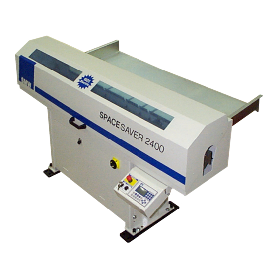
- Page 15 Chapter 1 – Description Main dimensions Fig.1.1 Main Dimensions of the Barfeeder SS2400T/S...
-
Page 16: Process Description
Chapter 1 – Description PROCESS DESCRIPTION SS2400T/S barfeeder feeds bars into the lathe as follows: • The loading mechanism takes a bar from the magazine and puts it into a fixed loading channel. • The flag shifts the bar into the spindle and after it returns to back limit position. •... - Page 17 Chapter 1 – Description SS2400T/S...
-
Page 19: Transport And Unpacking
Chapter 2 – Transport and Unpacking TRANSPORT AND UNPACKING Barfeeders are sealed in plastic sheet and transported on pallets or, exceptionally, in wooden boxes (see Chapter 1.4 for dimensions). They are fastened by screws to the box bottom/pallet. To eliminate any damage, the following procedure must be observed during unpackaging, otherwise the manufacture will bear no liability for any damage in unpackaging not carried out according to this procedure. - Page 20 Chapter 2 – Transport and Unpacking In unpacking check the completeness of standard accessories. . Standard accessories of the barfeeder SS2400T/S Type Quantity anchor bolts washers under anchor bolts setting kit setting wrench (speeder) cellulose thinner reducible repair paint User Manual pusher with fixed stopper ∅10 mm pusher with fixed stopper ∅18 mm See the packing list for complete list of the delivered accessories.
-
Page 21: Installation
Chapter 3 – Installation INSTALLATION PREPARATION It is appropriate for easy and quick installation that the installation and the first start-up of the barfeeder should be carried out by the manufacturer's technician or a by a person authorized by the manufacturer. It is in the user's interest to ensure presence of the barfeeder operation and maintenance staff during installation in order for them to be familiarized with the principles of the barfeeder use in collaboration with the lathe. -
Page 22: Barfeeder Alignment
Chapter 3 – Installation BARFEEDER ALIGNMENT 3.2.1 GENERAL Barfeeder alignment with regard to the lathe is the most important installation step and must be carried out as thoroughly as possible. The time spent by this process is negligible compared to possible damage to the lathe or the barfeeder in wrong alignment. Proper alignment of the barfeedeer is important for its trouble-free run. -
Page 23: Geometric Alignment With The Lathe
Chapter 3 – Installation 3.2.3 GEOMETRIC ALIGNMENT WITH THE LATHE Fig.3.2 Setting Kit SS2400T/S... - Page 24 Chapter 3 – Installation Preparation • Dismantle the pusher. • Install setting jigs, see Fig.3.2. Part 3.2/1 into the clamping device of the lathe. Part 3.2/3 into the front grip of the pusher. Part 3.2/4 into the rear grip of the pusher. •...
-
Page 25: Electrical Connection
Chapter 3 – Installation Anchoring After proper alignment, fasten the Barfeeder to the ground by means of expansion anchor screws (2 per each leg). • Drill holes according dimensions of the delivered anchor screws. holes must be sufficiently deep. The screws must not seat on the bottom of the hole. -
Page 26: Magazine Installation
Chapter 3 – Installation MAGAZINE INSTALLATION • Release the table cover switch SQ32 from its transport position in the loader pan and let it freely suspended on the cable. • Unscrew the right Allen head screw 3.5/1. • Remove the upper galvanized plate from the magazine frame. •... -
Page 27: Operation
Chapter 4 – Operation OPERATION PRIMARY PREREQUISITES 4.1.1 PUTTING INTO OPERATION, ANCHORING, ALIGNMENT The barfeeder must be thoroughly installed according to Chapter 3. 4.1.2 SAFETY OF OPERATION Interface and safety circuits between the lathe and the barfeeder must be properly connected and checked. -
Page 28: Feeding To Position (Ss2400S)
Chapter 4 – Operation 4.2.2 FEEDING TO POSITION (SS2400S) In this mode the barfeeder feeds the bar to a position set in the barfeeder. In this case the stopper is not needed. At change of workpiece parameters: At change of the bar diameter: Change the spindle insert. -
Page 29: Bar Feeding
Chapter 4 – Operation BAR FEEDING Bars are as a rule fed by the pusher into the lathe workspace. The lathe spindle must not turn during feeding. If the parameter #011 is set to Magazine Only (SS2400S), it is possible to feed the bar using e.g. -
Page 30: Installation Or Replacement Of Spindle Insert (At Change Of The Bar Diameter)
Chapter 4 – Operation INSTALLATION OR REPLACEMENT OF SPINDLE INSERT (AT CHANGE OF THE BAR DIAMETER) The user shall ensure appropriate spindle inserts, see Chapter 4.3. How to replace the spindle insert • In the manual mode, move the pusher into the upper limit position. •... -
Page 31: Pusher
Chapter 4 – Operation 1/10 of the bar dia. Fig.4.4 Magazine Position Setting PUSHER Barfeeders SS2400T/S are delivered with the following pushers: Pusher Bar ∅ SS2400T SS2400S ∅ 6 mm with fixed stopper 6 – 15 mm option option ∅ 10 mm with fixed stopper 12 –... -
Page 32: Barfeeder Control
Chapter 4 – Operation BARFEEDER CONTROL All controls of the barfeeder SS2400T/S are on the control panel. PLC panel E-Stop panel Fig.4.6 Control Panel 4.9.1 E-STOP PANEL E-Stop panel is located on the left part of the control panel, and is used for the control of safety elements of the barfeeder. -
Page 33: Keys
Chapter 4 – Operation 4.9.2 KEYS Function key meaning Numeric keys Function keys Enter key More key Esc key Mode keys Navigation keys Start/Stop key Info key Fig.4.7 Keys 4.9.2.1 MODE KEYS AUT, MAN, DAT Mode Meaning Automat It is possible to run the barfeeder in the automatic cycle. Manual It is possible to drive the barfeeder manually using the navigation keys. -
Page 34: Info Key
Chapter 4 – Operation 4.9.2.4 INFO KEY The key (Info) calls barfeeder diagnostics and other information on the machine such as barfeeder software options etc. Using this key it is possible to enter a service password which makes the machine service parameters accessible for writing. 4.9.2.5 NAVIGATION KEYS Navigation keys have generally the following meaning. -
Page 35: Status Bar
Chapter 4 – Operation 4.9.3 STATUS BAR In the manual and automatic mode in the upper part of the display there is a status bar which displays information, see Režim Mode Fig. 4.8. Interface Stav baterie Interface State of battery Počítadlo tyčí... -
Page 36: User Levels And Their Meaning
Chapter 4 – Operation 4.9.4 USER LEVELS AND THEIR MEANING Level Password Meaning Operator level is so called permanent level i.e. after the barfeeder Operator restart just the operator level is always activated. This means that password the user always has only the operator's rights following the barfeeder switching on. -
Page 37: Manual Mode
Chapter 4 – Operation 4.9.5 MANUAL MODE Manual mode allows barfeeder motions by means of the navigation keys. This mode is also used for the move to a reference and for the calibration of the material switch (SS2400S). 4.9.5.1 MOVE TO A REFERENCE Always after the barfeeder switching on, first it is necessary to go to a reference point. -
Page 38: Loader Reversing
Chapter 4 – Operation 4.9.5.3 LOADER REVERSING In case of need it is possible to reverse the loading mechanism. Use reversing in the loading mechanism motion in non-standard situations (bar jammed), when it is necessary to reverse the loading mechanism. How to reverse the loader •... -
Page 39: Automatic Mode
Chapter 4 – Operation 4.9.6 AUTOMATIC MODE Automatic mode is used for start-up of fully automatic working cycle of the barfeeder. Bar handling method Bar counter setting Current job Bar length Feeding force setting Fig.4.9 Automatic Mode 4.9.6.1 INDICATOR OF BAR HANDLING METHOD In the automatic mode, an indicator of the method of bar handling by the barfeeder is displayed in the upper part of the screen;... -
Page 40: Bar Counter
Chapter 4 – Operation 4.9.6.4 BAR COUNTER The bar counter is used for the setting of the number of bars loaded from the magazine, which still have to be machined by the lathe. The bar counter state is displayed on the status bar, see Chapter 4.9.3. -
Page 41: Lathe Operation Without The Barfeeder
Chapter 4 – Operation Even if the above described procedure is observed, a lathe error may arise. It may be caused by exceeding of permitted M-code time in the lathe. If the barfeeder feeds only to the "open clamping device" (without M- code), it will send an error message no. -
Page 42: Barfeeder Parameters
Chapter 4 – Operation 4.10 BARFEEDER PARAMETERS Barfeeder operation is controlled by parameters, which are divided into the following groups. • Operator Parameters • Service Parameters Operator Parameters are technological parameters. The values of the technological parameters can be stored as so called jobs in the Jobs Table and reload them into the barfeeder memory, see below. -
Page 43: Parameter Types
Chapter 4 – Operation 4.10.1.2 PARAMETER TYPES 4.10.1.2.1 PARAMETERS OF LIST TYPE The parameters of list type are enumerative parameters #000 to #099. Current value of these parameters is identified by . How to change the value of the list type parameter •... -
Page 44: Operator Parameters
Chapter 4 – Operation 4.10.2 OPERATOR PARAMETERS Operator parameter setting is directly dependent on the part production technology in the lathe. Material to square up the new bar #100 ..End of Bar #101 ..Pusher Retract Position #102 ..Collet Face Position #105 ..First Feeding Length (SS2400S) #106 ..Second Feeding Length (SS2400S) #107 ..New Bar Face Position (SS2400S) - Page 45 Chapter 4 – Operation 4.10.2.1 #100 – END OF BAR Using the parameter #100 the barfeeder checks the bar length in the lathe and decides whether the bar is or is not sufficiently long to manufacture a part. H..part length with squarring allowance I ..
-
Page 46: 300 - Feeding Force
Chapter 4 – Operation 4.10.2.3 #300 – FEEDING FORCE Parameter #300 sets forth a maximum force, by which the barfeeder will push the bar to the stopper, eject the bar rest, slide the new bar in the spindle lathe, and go forward (toward the lathe) in the manual mode. -
Page 47: 107 - New Bar Face Position (Ss2400S)
Chapter 4 – Operation If the barfeeder runs in the Magazine Mode (#011), it alternates the feeding length in the same way. However the difference is that in this mode the barfeeder does not go with the pusher into the spindle, but only deducts relevant feeding length from the bar length in the lathe. See the parameter #011 for details. -
Page 48: 102 - Collet Face Position
Chapter 4 – Operation 4.10.2.8 #102 – COLLET FACE POSITION Parameter #102 sets the distance of the clamping device face from the barfeeder (from the end of the pusher in the back position). In setting this parameter it is necessary to observe the following procedure, which ensures correct setting of clearances, and thus correct setting of the parameter #102. -
Page 49: 003 - End Of Bar M-Code (Eob M-Code)
Chapter 4 – Operation 4.10.2.10 #003 – END OF BAR M-CODE (EOB M-CODE) Parameter #003 defines the barfeeder behaviour in situation, when the clamping device is closed and the lathe sends the M-code. If the lathe sends the M-code at the clamping device closed, the M-code is not understood as a feed command, but as an end of bar test. -
Page 50: 004 - Ejecting Control
Chapter 4 – Operation 4.10.2.11 #004 – EJECTING CONTROL Parameter #004 influences the way of ejecting the rest of bar into the lathe workspace. #004 Description In this case the rest of bar can be ejected in the following ways: •... - Page 51 Chapter 4 – Operation Identical job Selected job Job saving key Job download key Job deletion key Fig.4.13 Jobs Table Identical job The identical job field displays the number of the first found job, which content is identical to the content of technological parameters in the memory of the barfeeder. Using the identical job you can determine whether the given combination of parameters is already saved in the Jobs Table.
-
Page 52: Service Parameters
Chapter 4 – Operation 4.10.3 SERVICE PARAMETERS Service parameters are parameters which do not relate to the method of part making in the lathe. These parameters influence the timing of the interface signals, user interface and other important features of the barfeeder. Common user should not change the service parameter settings. -
Page 53: Automatic Mode Simulation
Chapter 4 – Operation 4.10.3.1.2 AUTOMATIC MODE SIMULATION Simulation mode is used for the testing of the newly installed barfeeder at the lathe without the need of feeding an actual bar. By the simulation it is possible to test mutual compatibility of the barfeeder and lathe interfaces. -
Page 54: Test Mode
Chapter 4 – Operation Simulation mode activation • Change the user level to service level and set the parameter #000 to Simulation . • Put the barfeeder into the basic position the automatic cycle starts from. The pusher must be in the low rear position. •... -
Page 55: 001 - Feeding On M-Code
Chapter 4 – Operation 4.10.3.2 #001 – FEEDING ON M-CODE Parameter #001 determines whether the barfeeder is to begin the feeding only at the clamping device open or to wait to a special command sent from the lathe. #001 Description The barfeeder feeds to a special command (M-code) sent from the lathe. -
Page 56: 005 - Clamping Device
Chapter 4 – Operation 4.10.3.4 #005 – CLAMPING DEVICE Parameter #005 sets the logic of the open clamping device. #005 Description Standard Clamping device is open, if the signal is ON. The clamping device is closed, if the signal is OFF. Inverse Clamping device is open, if the signal is OFF. -
Page 57: 103 - Barfeeder Stroke
Chapter 4 – Operation such quickly sent M-codes could "merge" in one code. The barfeeder is able to distinguish the M-code leading edge only if it does not report the M-code end to the lathe. For this reason it is recommended to set the parameter #008 to Static on new lathes. In every case the lathe should not begin to send the new M-code in approx. - Page 58 Chapter 4 – Operation #004 #005 Standard Standard #006 English English #007 #008 Static Static #009 No Reset No Reset #010 Stopper #011 Barfeeder #100 0 mm 0 mm #101 30 mm 30 mm #102 500 mm 500 mm #103 1640 mm 1640 mm #105...
-
Page 59: How To Program A Lathe With The Barfeeder
Chapter 4 – Operation 4.11 HOW TO PROGRAM A LATHE WITH THE BARFEEDER There are many ways of programming a lathe with the barfeeder SS2400T/S. Generally, the End of Bar test should be in the program before feeding to ensure that an arbitrarily long bar can be clamped in the lathe at start of the automatic cycle. -
Page 60: Feeding To Position (Ss2400S)
Chapter 4 – Operation 4.11.2 FEEDING TO POSITION (SS2400S) If end of bar is not reached, the barfeeder moves the bar by a pre-programmed feeding length. The end of bar initiates the bar replacement subprogram. Main program (feeding) 1. Tool head departure to safe position 2. -
Page 61: Parameter Setting Example
Chapter 4 – Operation 4.11.3 PARAMETER SETTING EXAMPLE Example – Single feeding Allowance for bar squaring after feeding 10 3 Task: Produce a part long 15 mm from the bar ∅ 50 mm. Allowance for bar squaring after feeding is 0.3 mm, the width of the cut-off tool is 3 mm. - Page 62 Chapter 4 – Operation Feeding by the 2nd spindle of the lathe; new bar loading to stopper (SS2400S) Parameter Value Note #100 48.3 mm 48.3 = 15 + 3 + 0.3 + 30 #101 Depends on the pusher sag. #300 35 % #010 Stopper...
-
Page 63: Maintenance
Chapter 5 Maintenance MAINTENANCE ROUTINE MAINTENANCE Weekly Remove any dirt from the barfeeder. Monthly 11 Clean the section, guide bars and rolling guide rollers. Grease the guide bars with grease LV2. 12 Lubricate the pusher tilting bearings with machine oil. 13 Clean and oil the pusher lock bar and pin. -
Page 64: Error Messages
Chapter 5 Maintenance ERROR MESSAGES If the barfeeder evaluates certain situation as PLC status an error status, an error message is displayed on the control panel. Cancel the error by the key PLC status In certain cases error messages contain PLC status (xxx-xxx-xxx). - Page 65 Chapter 5 Maintenance Error Cause Corrective Action In the automatic mode the barfeeder Check that the lathe reacts correctly to the monitors the lathe reaction to the M- M-fin signal sent from the barfeeder (K7 M-code isn't finished fin signal. If the lathe does not relay).
- Page 66 Chapter 5 Maintenance Error Cause Corrective Action Maximum permitted time of the Check that no obstacle is in the way of the loading mechanism motion loader motion. Loader is too slow exceeded (↑ max. 7 s, ↓ max. 3 s). Check fuse F3.
- Page 67 Chapter 5 Maintenance Error Cause Corrective Action SM1 drive of M1 motor signalled an error. If the drive is not reset, it is Servo drive fault possible to read the drive error directly on the SM1 drive see Chapter Error! Reference source not found..
-
Page 68: Electric Equipment
Chapter 5 Maintenance ELECTRIC EQUIPMENT 5.3.1 ARRANGEMENT AND PURPOSE OF SWITCHES SQ32 A (PLC) SQ23 S1, S3, S10 M1, E1 Fig.5.2 Electric Element Layout Switch Name Description SQ23 Cover switch If the key S3 is in AUT position, the switch SQ23 switches of the safety relay K1, thus casing emergency stop of the barfeeder. -
Page 69: Arrangement Of Instruments In The Switchboard
Chapter 5 Maintenance 5.3.2 ARRANGEMENT OF INSTRUMENTS IN THE SWITCHBOARD F1, F2 F3, F4, F5 Fig.5.3 Arrangement of Instruments in the Switchboard 5.3.3 CONTROL Barfeeder control is ensured by PLC PP35 (hereinafter only PLC) integrated in the barfeeder control panel, which controls the SM1 drive and power elements of the X3 module in the barfeeder switchboard. -
Page 70: Battery
Chapter 5 Maintenance 5.3.3.1.1 BATTERY Battery life The battery makes it possible to save the user set data in the PLC memory, when the barfeeder is switched off. Under normal operation the battery life is approx. 5 years. Battery condition is displayed in the status bar. After expiration of the assumed battery life, it is desirable to replace it preventively, even if the battery status indicator has not indicates the end of its life. -
Page 71: Drive Sm1
Chapter 5 Maintenance 5.3.3.3 DRIVE SM1 Drive setting Switch State SW1/P8 SW1/P7 Drive settting SW1/P6 SW1/P5 Drive state SW1/P4 SW1/P3 SW1/P2 SW1/P1 Fig.5.5 Drive SM1 5.3.3.3.1 SELECTED STATES OF THE DRIVE Status Meaning Base Block Servo OFF Servo ON Servo ON Overload Overload You can get a complete list of the drive states from the barfeeder manufacturer (only in... -
Page 72: Interface Description
Chapter 5 Maintenance 5.3.4 INTERFACE DESCRIPTION You can find the diagram of standard interface connection in 5.3.6. Barfeeder power supply Single-cable interface X1/1, X1/2, X1/PE Twin-cable interface X2/1, X2/2, X2/PE Signals from the lathe to the barfeeder The signals from the lathe to the barfeeder should be implemented by contacts of relays or switches on the lathe side. - Page 73 Chapter 5 Maintenance Signals from the barfeeder to the lathe The signals from the barfeeder to the lathe are implemented by relay contacts in the barfeeder . The signals should be supplied with 24 VDC from the lathe (X1/19). Name Interface Description Barfeeder...
-
Page 74: Diagnostics
Chapter 5 Maintenance 5.3.5 DIAGNOSTICS Diagnostics of the barfeeder provides the user with an overview of the barfeeder PLC inputs and outputs and some other data see the following description. The diagnostics is activated by pressing the key and eventual listing using 5.3.5.1 DIAGNOSTIC DATA Data... -
Page 75: Wiring Diagrams
Chapter 5 Maintenance 5.3.6 WIRING DIAGRAMS 5-13 SS2400T/S... - Page 76 Chapter 5 Maintenance 5-14 SS2400T/S...
- Page 77 Chapter 5 Maintenance 5-15 SS2400T/S...
- Page 78 Chapter 5 Maintenance 5-16 SS2400T/S...
- Page 79 Chapter 5 Maintenance 5-17 SS2400T/S...
- Page 80 Chapter 5 Maintenance 5-18 SS2400T/S...
- Page 81 Chapter 5 Maintenance 5-19 SS2400T/S...
- Page 82 Chapter 5 Maintenance 5-20 SS2400T/S...
- Page 83 Chapter 5 Maintenance 5-21 SS2400T/S...
- Page 84 Chapter 5 Maintenance 5-22 SS2400T/S...
-
Page 85: Spare Parts
Chapter 5 Maintenance SPARE PARTS 5.4.1 ELECTRIC SPARE PARTS SQ32 A (PLC) S1, S3, S10 SQ23 K2,4,5,6,7 M1, E1 K11,12,14,15 A (PLC) Fig.5.5 Electric Spare Parts 5-23 SS2400T/S... - Page 86 Chapter 5 Maintenance Element English Czech Type 4PP035.0300-K04 Battery Baterie Proximity switch Indukční snímač XS1D12PA140D Transformer Transformátor YHT320, No.10206.004 p200,230,400V – s8,11,22V Rectifier Usměrňovač CNC/A17/10, 5,8,24VDC Safety relay Bezpečnostní relé XPSAF5130 Interface relay Relé interfacové G2R-2-SNI 24VDC Relay Relé G2RL-2 24VDC Feeding motor Motor podávací...
Need help?
Do you have a question about the SPACESAVER 2400T and is the answer not in the manual?
Questions and answers