Advertisement
Available languages
Available languages
Quick Links
Advertisement

Related Manuals for Waldbeck Ventura


Summary of Contents for Waldbeck Ventura
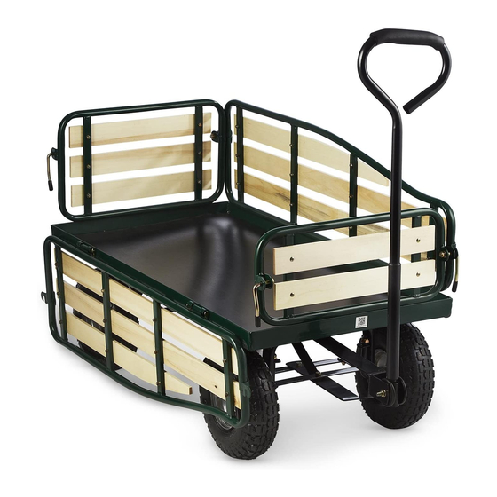
- Page 1 10030403 10034736 10034794 10034795 Ventura Bollerwagen Handcart Carros Chariots Carrelli...
- Page 3 Teileliste Bild Beschreibung Anzahl Boden Linke Seitenwand Rechte Seitenwand Vorderwand...
- Page 4 Rückwand Einlage Hintere Achshalterung Hintere Achsführung...
- Page 5 Vordere Achshalterung Mittlere Achsführung vorne Lenkanschluss Gabel Verbinder aus Kunst- stoff Zuggriff...
- Page 6 M8X18 Schraube + Unterlegschraube + Mutterschraube M8X25Schraube Unterlegschraube & Mutter M8X60 Schraube + Unterlegschraube + Mutter M11 Unterlegschrau- be & Bundbolzen Unterlegschraube M12+ Kontermutter Montagebolzen für die Wand+ M7-Unterlegscheibe + Federstecker...
-
Page 7: Montage
Montage Schritt 1 Zusammenbau der Hinterachse 1. Legen Sie den Boden (1) umgedreht hin. 2. Setzen Sie die hintere Achshalterung (8) an den Boden (1) an. Machen Sie die Bohrlöcher der hinteren Achshalterung (8) mit den Löchern auf dem hin- teren Teil des Bodens (1) bündig. - Page 8 Schritt 2 Zusammenbau der Vorderachse 1. Vordere Achshalterung (10) am Boden vorne (1) anbringen. Die Bohrungen ausrichten. Legen Sie eine Unterlegscheibe (16) über die Schrauben und schrauben Sie jeweils eine Mutter (16) auf das Gewinde. 2. Setzen die Gabel (13) auf die vordere Achshalterung (10), indem Sie die Schrauben der Gabel durch die Bohrungen der Achshalterung (10) führen.
- Page 9 3. Setzen Sie ein Ende der mittleren Achsführung (11) an den Boden (1) und das ande- re Ende an die vordere Achshalterung (10). Richten Sie die Bohrungen der vorderen Achshalterung (10), der mittleren Achsführung (vorn) und der Gabel (13) aus und führen Sie von unten M8x25-Schrauben hindurch.
- Page 10 Schritt 3 Montage der Räder 1. Setzen Sie die Räder (7) an die Enden der vorderen und hinteren Achshalterung (10 und 8). 2. Unterlegscheiben und Kontermuttern (20) an die Enden der Räder setzen. Schritt 4 Montage des Handzugs 1. Entfernen Sie die Schrauben M8x60 und die Muttern (18) von dem Kunststoffverbin- der (14).
- Page 11 2. Setzen Sie den Zusammenbau von Zuggriff (15) und den Verbinder (14) in die Gabel (13). Machen Sie die Bohrungen des Zuggrifs und dem Verbinder bündig. Führen Sie durch die Bohrungen Schrauben des Typs M8x60 und schrauben Sie sie mit Kontermuttern (18) fest.
- Page 12 4. Setzen Sie die Kunststoffeinlage in den Boden. 5. Klappen Sie die linke Wand (2) und die Rückwand (5) nach oben. Stellen Sie den Verriegelungshebel an der Hinterwand nach oben, so dass er in die Stange der Seitenwand greift. 6. Wiederholen Sie die Schritte für die verbleibenden Ecken des Wagens. Hersteller: Chal-Tec GmbH, Wallstr.
-
Page 13: Parts List
Parts List Picture Desription Base Left fence panel Right fence panel Front fence panel... - Page 14 Back fence panel Plastic liner Wheel Rear axle support Rear axle brace...
- Page 15 Front axle support Center front axle brace Steering link connector Yoke Plastic coupling Pull handle...
- Page 16 M8X18 bolt washer & nut M8X25 bolt & washer & nut M8X60 bolt & washer & nut M11 washer & collar pin M12 washer & Fence assembly bolt, M7 washer & R...
- Page 17 Assembly Step 1 Rear axle assembly 1. Turn the Base (1) upside down. 2. Place the Rear axle support (8) on the Base (1). Align the holes in the rear axle sup- port (8) with the holes at the rear of the base (1).. Insert an M8 x18 bolt (16) from under the cart and through the aligned holes.
- Page 18 Step 2 Front axle assembly 1. Place the front axle support (10) on the front of the Base (1). Align the holes in the front axle support (10) with the holes in the Base (1). Insert an M8 x 18 bolt (16) from under the cart and through the aligned holes.
- Page 19 3. Place one end of Front axle brace (11) on the base (1), and the other end on the front axle support (10). Aligned the holes on the Front axle support (10), centre front axle brace (11) and yoke (13), and then insert an M8x 25 bolt from under side, and attach an M8 washer and a M8 nut (17).
- Page 20 Step 3 Wheel assembly 1. Place the wheels (7) onto the ends of the front and rear axle supports (10& 8). 2. Insert an M12 washer and a lock nut (20) onto the ends of each wheel. Step 4 Pull handle assembly 1.
- Page 21 2. Place the Pull handle (15) and plastic coupling (14) assembly into the Yoke (13). Align the holes in the Pull handle (15) and Plastic coupling (14) with the holes on the yoke (13). Insert the M8x60 bolt through the aligned holes and secure the connec- tion with an M8 lock nut (18).
- Page 22 4. Place the plastic liner (6) into the base (1). 5. Pull the Left Fence panel (2) and Back fence panel(5) up, and turn the lock handle on the Back fence panel(5)so that it fits snugly into the hinge at the corner of the Left Fence panel(2).
Need help?
Do you have a question about the Ventura and is the answer not in the manual?
Questions and answers