
Related Manuals for CGC BULLDOG InnKeeper

Summary of Contents for CGC BULLDOG InnKeeper
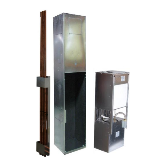
- Page 1 Installation Operation Maintenance Manual Vertical Stack Units (Universal Cabinet) InnKeeper/HomeKeeper Models: IKV 008-018 IEV 008-012 HKV 016-036 HEV 016-036 www.bulldogheatpump.com...
-
Page 2: Table Of Contents
Generic Wiring Diagram for IKV008-018 Units………..………..……………………….……..….…………………… Generic Wiring Diagram for HKV016-036 Units...………………………………...……………….…..……………..InnKeeper Universal Cabinet Template………..…..…..………………..………...……...………..….. HomeKeeper Universal Cabinet Template………...………...……………....………..………..……….. Diagnosis Table………..………..……………………………………………………..…………………..…..…….... © Copyright 2013 CGC Group Inc. Installation Operation Maintenance Manual is Subject to Change without Notice. Last Revised: Aug, 2020... -
Page 3: Information
If the unit was previously in use, ensure that all water in the coil has been blown out and that all hose connections are plugged during storage. © Copyright 2013 CGC Group Inc. Installation Operation Maintenance Manual is Subject to Change without Notice. Last Revised: Aug, 2020... -
Page 4: Model Nomenclature
Vertical Stack Units (Universal Cabinet) – Installation Operational Manual Model Nomenclature © Copyright 2013 CGC Group Inc. Installation Operation Maintenance Manual is Subject to Change without Notice. Last Revised: Aug, 2020... -
Page 5: Refrigerant Charge
The installing contractor will be responsible for removing the unit if it is not serviceable in place. © Copyright 2013 CGC Group Inc. Installation Operation Maintenance Manual is Subject to Change without Notice. Last Revised: Aug, 2020... -
Page 6: Unit Installation
45⁰F (7⁰C). Do not locate the unit in areas that may be subjected to freezing temperatures. © Copyright 2013 CGC Group Inc. Installation Operation Maintenance Manual is Subject to Change without Notice. Last Revised: Aug, 2020... -
Page 7: Cabinet Placement
(See Figure 2). If installing a base extension, bolt the extension to the concrete floor (See Figure 3). 3. The riser knockout to be left exposed for riser installation. Figure 2 Figure 3 © Copyright 2013 CGC Group Inc. Installation Operation Maintenance Manual is Subject to Change without Notice. Last Revised: Aug, 2020... -
Page 8: Riser Bundle Installation (When Ordered)
11. A fire stop may be required for the riser openings in the floors. Consult local fire codes for dictation on appropriate requirements. Figure 5 © Copyright 2013 CGC Group Inc. Installation Operation Maintenance Manual is Subject to Change without Notice. Last Revised: Aug, 2020... - Page 9 Vertical Stack Units (Universal Cabinet) – Installation Operational Manual Riser Drawing Figure 6 © Copyright 2013 CGC Group Inc. Installation Operation Maintenance Manual is Subject to Change without Notice. Last Revised: Aug, 2020...
-
Page 10: Electrical Wiring
See Figure 8 for Standard Control wiring of a single stage heat, single stage cool thermostat wiring. Figure 8 Figure 7 © Copyright 2013 CGC Group Inc. Installation Operation Maintenance Manual is Subject to Change without Notice. Last Revised: Aug, 2020... -
Page 11: Dry Walling And Chassis Installation
9. Wire thermostat to control board. Connect power cord at cabinet electrical box. Figure 9 Figure 10 © Copyright 2013 CGC Group Inc. Installation Operation Maintenance Manual is Subject to Change without Notice. Last Revised: Aug, 2020... -
Page 12: Unit Operation - In Suite
Stage 2 Heating: After 10 minutes, if set-point temperature is not reached, fan will automatically step up and operate at high speed. © Copyright 2013 CGC Group Inc. Installation Operation Maintenance Manual is Subject to Change without Notice. Last Revised: Aug, 2020... - Page 13 2 degrees and cooling to 4 degrees. This will help to ensure the unit operates minimally; preventing your suite from becoming excessively cold or hot. © Copyright 2013 CGC Group Inc. Installation Operation Maintenance Manual is Subject to Change without Notice. Last Revised: Aug, 2020...
-
Page 14: Standard Panel And Boot Installation
2. Locate the boot and lock it into place at the base of the unit using the lower clips to secure it. 3. Hang the front panel on upper clips. Lock front panel into top of boot. © Copyright 2013 CGC Group Inc. Installation Operation Maintenance Manual is Subject to Change without Notice. Last Revised: Aug, 2020... -
Page 15: Operation - Detailed
Ta, Tr, And Tw are 10k Ohm NTP thermistors, while Co is a 100 Ohm NPT thermistor. These Inputs do not have LED indicators. © Copyright 2013 CGC Group Inc. Installation Operation Maintenance Manual is Subject to Change without Notice. Last Revised: Aug, 2020... - Page 16 If the head pressure exceeds the set point of the high pressure switch, it will open, and the control board will terminate the compressor operation within 10 seconds. At this © Copyright 2013 CGC Group Inc. Installation Operation Maintenance Manual is Subject to Change without Notice. Last Revised: Aug, 2020...
- Page 17 30 seconds, and then restarted. At this time a flash code of 7 will be initiated. The 4 minute cycle will continue until the © Copyright 2013 CGC Group Inc. Installation Operation Maintenance Manual is Subject to Change without Notice. Last Revised: Aug, 2020...
- Page 18 The BULLDOG control board has been designed to operate with most standard 24V AC thermostats. These are powered from the CGC board with 24V AC and simply switch power ON to each of the Heat (W), Cool (Y), Fan (G) or Aux (A). While most present day thermostats operate in this manner there are others that may or may not work properly.
-
Page 19: Commission And Start Up
System water should have a neutral pH balance of approximately 7.5 which will extend the life of the hoses, heat exchangers, and other water side accessories. © Copyright 2013 CGC Group Inc. Installation Operation Maintenance Manual is Subject to Change without Notice. Last Revised: Aug, 2020... - Page 20 The factory reserves the right to refuse warranty if these details are not provided. © Copyright 2013 CGC Group Inc. Installation Operation Maintenance Manual is Subject to Change without Notice. Last Revised: Aug, 2020...
- Page 21 Based on this information the factory may request the charge be adjusted or the refrigeration components be adjusted to optimize cooling operation. © Copyright 2013 CGC Group Inc. Installation Operation Maintenance Manual is Subject to Change without Notice. Last Revised: Aug, 2020...
-
Page 22: Maintenance
Make sure to inspect and clean if necessary, the condensate hose and drain pan on a regular basis. Refer to BULLDOG Diagnosis table for more details, Page 29. © Copyright 2013 CGC Group Inc. Installation Operation Maintenance Manual is Subject to Change without Notice. Last Revised: Aug, 2020... -
Page 23: Details
Vertical Stack Units (Universal Cabinet) – Installation Operational Manual Details IKV Universal Cabinet Detail Drawing © Copyright 2013 CGC Group Inc. Installation Operation Maintenance Manual is Subject to Change without Notice. Last Revised: Aug, 2020... -
Page 24: Homekeeper Universal Cabinet Detail Drawing
Vertical Stack Units (Universal Cabinet) – Installation Operational Manual HKV Universal Cabinet Detail Drawing © Copyright 2013 CGC Group Inc. Installation Operation Maintenance Manual is Subject to Change without Notice. Last Revised: Aug, 2020... -
Page 25: Generic Wiring Diagram For Ikv008-018 Units
Vertical Stack Units (Universal Cabinet) – Installation Operational Manual Generic Wiring Diagram for IKV008-018 Units © Copyright 2013 CGC Group Inc. Installation Operation Maintenance Manual is Subject to Change without Notice. Last Revised: Aug, 2020... -
Page 26: Generic Wiring Diagram For Hkv016-036 Units
Vertical Stack Units (Universal Cabinet) – Installation Operational Manual Generic Wiring Diagram for HKV016-036 Units © Copyright 2013 CGC Group Inc. Installation Operation Maintenance Manual is Subject to Change without Notice. Last Revised: Aug, 2020... -
Page 27: Innkeeper Universal Cabinet Template
Vertical Stack Units (Universal Cabinet) – Installation Operational Manual InnKeeper Universal Cabinet Template © Copyright 2013 CGC Group Inc. Installation Operation Maintenance Manual is Subject to Change without Notice. Last Revised: Aug, 2020... -
Page 28: Homekeeper Universal Cabinet Template
Vertical Stack Units (Universal Cabinet) – Installation Operational Manual HomeKeeper Universal Cabinet Template © Copyright 2013 CGC Group Inc. Installation Operation Maintenance Manual is Subject to Change without Notice. Last Revised: Aug, 2020... -
Page 29: Diagnosis Table
Vertical Stack Units (Universal Cabinet) – Installation Operational Manual Diagnosis Table © Copyright 2013 CGC Group Inc. Installation Operation Maintenance Manual is Subject to Change without Notice. Last Revised: Aug, 2020...
Need help?
Do you have a question about the BULLDOG InnKeeper and is the answer not in the manual?
Questions and answers