Table of Contents
Advertisement
Quick Links
Design Manual
Installation • Operation • Maintenance
Model F120
Triple-Mode UV/IR
Flame Detector
70053
23282 Mill Creek Drive, Suite 215
Laguna Hills, CA 92653 USA
+1.949.583.1857 Phone
+1.949.340.3343 Fax
www.safetysys.com
support@safetysys.com
The information and technical data disclosed by this document may be used and disseminated only for the
purposes and to the extent specifically authorized by Safety Systems Technology in writing. Such information and
technical data are proprietary to Safety Systems Technology and may not be used or disseminated except as
provided in the foregoing sentence.
Advertisement
Table of Contents

Summary of Contents for SST F120
- Page 1 Design Manual Installation • Operation • Maintenance Model F120 Triple-Mode UV/IR Flame Detector 70053 23282 Mill Creek Drive, Suite 215 Laguna Hills, CA 92653 USA +1.949.583.1857 Phone +1.949.340.3343 Fax www.safetysys.com support@safetysys.com The information and technical data disclosed by this document may be used and disseminated only for the purposes and to the extent specifically authorized by Safety Systems Technology in writing.
- Page 2 Blank Page...
-
Page 3: Table Of Contents
Quick Finder MODEL F120 UV/IR Triple-Mode Flame Detector SAFETY INFORMATION ................... 120-3 QUICK INSTALLATION GUIDE ................. 120-4 TOOLS REQUIRED ......................120-4 QUICK INSTALL GUIDE ....................120-4 GENERAL DESCRIPTION ................120-8 TRIPLE MODE UV/IR ....................120-8 USER CUSTOMIZABLE MODES .................120-9 PHYSICAL DESCRIPTION ..................120-9 OPERATIONAL DESCRIPTION ..................120-9 SPECIFICATIONS ................... - Page 4 14. INSTALL ACCESSORIES ..................120-39 ROUTINE OPERATION ................. 120-40 LED INDICATOR ......................120-40 NORMAL OPERATION ....................120-40 ALARM AND DELAYED ALARM MODE ..............120-40 SYSTEM FAULT ......................120-41 MAINTENANCE ..................... 120-42 FACTORY RECOMMENDED MAINTENANCE ............120-42 MONTHLY OPERATION TEST ...................120-42 QUARTERLY LENS CLEANING ................120-43 FRONT AND REAR THREAD LUBRICATION ............120-43 O-RING LUBRICATION....................120-43 ANNUAL VERIFICATION ....................120-43 MONTHLY OPERATING TEST INSTRUCTIONS ...........
-
Page 5: Safety Information
Model F120 UV/IR Flame Detector MODEL F120 UV/IR Triple-Mode Flame Detector SAFETY INFORMATION Please read and understand this Design Manual BEFORE installing, operating, or conducting maintenance on the flame detector. Pay close attention to important messages marked as WARNINGS and IMPORTANT throughout the Design Manual. -
Page 6: Quick Installation Guide
Model F120 UV/IR Flame Detector QUICK INSTALLATION GUIDE Tools Required 4 mm hex wrench is required. Flat head screwdriver 3/16 inch (5 mm) width for terminal block connections. Adjustable wrench for conduit or cable gland connections. WARNING: De-classify the area to reduce the risk of ignition of hazardous atmosphere. - Page 7 Model F120 UV/IR Flame Detector Wall or Ceiling Mounting Bracket Conduit Mounting Bracket Conduit Mounting Assembly 4. Run the wires through the rear housing conduit opening of the flame detector 5. Wire and connect the detector to earth ground (see Wiring Diagrams on next pages) 6.
- Page 8 Model F120 UV/IR Flame Detector Wiring Diagram 120-4 January, 2016...
- Page 9 Model F120 UV/IR Flame Detector January, 2016 120-5...
-
Page 10: General Description
UV/IR detectors which are subject to the aforementioned interferences. The F120 flame detector monitors for specific radiation emitted by a fire through the use of 3 sensors - one UV (ultraviolet) sensor and two IR (infrared) sensors. The UV sensor provides the shortest response time in detecting radiation from a fire. -
Page 11: User Customizable Modes
This provides a rapid visual check of detector operation and indicates the unit is in operation. The Model F120 Flame Detector responds to a flame with a variety of criteria and time delay settings. A multiposition selector switch sets the detector for the most appropriate mode for the exact conditions at your particular installation. - Page 12 Model F120 UV/IR Flame Detector Alarm and Delayed Alarm The Model F120’s standard configuration requires at least two of its three sensors to be activated to signal an alarm. When flame radiation is initially detected, the Alarm outputs, both relay contact and current loop, are instantly activated. A red LED alarm light behind the viewing window in the detector is also activated.
-
Page 13: Specifications
Model F120 UV/IR Flame Detector SPECIFICATIONS System Specifications Spectral Response ....UV: 185 to 245 nm 4.3 microns (Hydrocarbon CO spike) Detection Range ....Reliably detects a one square foot n-Heptane fire at a distance of 70 feet / 20 meters Response Time ..... -
Page 14: Environmental Specifications
Model F120 UV/IR Flame Detector Environmental Specifications Operating Temperature ..-40°F to 185°F (-40°C to 85°C) Operating Humidity ....0-100% RH, non-condensing Ingress Protection ....IP66 Mechanical Specifications Dimensions ......4.40 x 5.25 inches (112 x 133 mm) Weight ........4.0 lbs (1.8 kg) Aluminum 10.0 lbs (4.5 kg) Stainless Steel... -
Page 15: Selecting A Location For The Flame Detector
The distance at which the flame detector will respond to a fire is a function of the intensity of that fire. The F120 has a maximum detection range of 70 feet (21 m) for an n-Heptane fire with a surface area of 1 sq ft (0.093m... - Page 16 Model F120 UV/IR Flame Detector 120-12 January, 2016...
- Page 17 Model F120 UV/IR Flame Detector January, 2016 120-13...
- Page 18 Model F120 UV/IR Flame Detector 120-14 January, 2016...
- Page 19 Model F120 UV/IR Flame Detector January, 2016 120-15...
-
Page 20: Orientation Of The Flame Detector
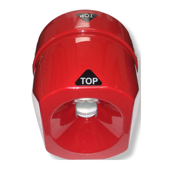
The F120 detector housing is marked “TOP” to identify the recommended side of the detector that should be mounted facing up. This orientation prevents the accumulation of dust and/ or debris on the lens and the self-test oriface. -
Page 21: Required Quantity Of Flame Detectors
Model F120 UV/IR Flame Detector Required Quantity of Flame Detectors The F120 has a cone of vision of 90° and a coverage area of 70 feet within its center axis. Your specific application will determine the number of flame detectors required to protect an area or monitor an area or equipment. - Page 22 Model F120 UV/IR Flame Detector Sunrise and Sunset In outdoor applications, orient the flame detector so that it is pointing directly in a north facing or south facing direction. This will insure that the detector will never see the sun as it rises above the horizon or sets below the horizon.
-
Page 23: Electrical Wiring
Model F120 UV/IR Flame Detector ELECTRICAL WIRING The 0-20 mA analog output on the F120 is wired in Current SOURCE configuration. Terminal Connections Terminal Marking Connection Description Number SPARE SPARE SPARE RESET ALARMS Remote Reset Resets Latched Alarm Relays 0-20 mA OUTPUT... -
Page 24: Power
Model F120 UV/IR Flame Detector Power The Model F120 requires a power supply of between 20 VDC and 35 VDC. A minimum supply of 20 VDC is required at the detector, taking into account the voltage drop due to cable resistance. Each F120 draws 125 mA continuously from the power supply. Current draw increases to 230 mA when in alarm. -
Page 25: Default Configuration
Model F120 UV/IR Flame Detector DEFAULT CONFIGURATION The Model F120 UV/IR Flame Detector is supplied with the following default configuration. Function Setting Description Sensor Type UV and IR Pre-assembled Signal Output 0 mA Power Fault 2 mA Malfunction 4 mA... -
Page 26: Installation
Model F120 UV/IR Flame Detector INSTALLATION 1. Shipment Flame detectors shipped by Safety Systems Technology is fully assembled, quality tested and packaged in special containers to protect against physical damage. Upon receipt of the shipment, contents should be carefully removed and checked against the packing list. -
Page 27: 4-A. Install The Conduit Swivel Mounting Bracket
Model F120 UV/IR Flame Detector 12. Use a 4 mm hex wrench to loosen the locking screw on the rear of the detector housing 13. Unscrew the front housing from the rear housing 14. Remove the electronics module from the rear terminal blocks by gently rocking the board side-to-side. -
Page 28: 4-B. Install The Wall/Ceiling Mounting Bracket
Model F120 UV/IR Flame Detector Conduit Mounting Assembly 5. Pull the wires through the conduit and out through the rear housing. 4-B. Install the Wall/Ceiling Mounting Bracket For Cable Gland Installation 1. Install the Wall/Ceiling Mounting Bracket at the desired location. The mounting bracket has a square mounting base for solid surfaces, 2.5”... -
Page 29: Wire The Detector
Model F120 UV/IR Flame Detector 4. Run the cable assembly to the location of the flame detector. 5. Use a suitable cable gland with a 3/4 inch NPT male thread installed in the conduit opening of the flame detector. 6. Run the wires through the cable gland and through the rear housing of the flame detector. -
Page 30: Terminal Connections
Model F120 UV/IR Flame Detector Factory Recommended Wires Use 16 or 18 AWG (1.5 or 0.75 mm ) wires whenever possible. Terminal Connections Terminal Marking Connection Description Number SPARE SPARE SPARE RESET ALARMS Remote Reset Resets Latched Alarm Relays 0-20 mA OUTPUT... - Page 31 Model F120 UV/IR Flame Detector Wiring Diagram January, 2016 120-27...
- Page 32 Model F120 UV/IR Flame Detector 120-28 January, 2016...
-
Page 33: Alarm Contact Relays Connection
Model F120 UV/IR Flame Detector Alarm Contact Relays Connection Wire your external equipment to the following terminals to activate the Alarm contact relays as desired. Normally Open Terminal Marking Connection Number CLOSED ON ALARM Contacts set to Normally Open and... -
Page 34: Connect The Detector To Earth Ground
A Ground Terminal is provided on both the inside and outside walls of the rear housing for use in applications where the conduit does not provide adequate grounding to the F120, or the System Designer determines that additional grounding is required. - Page 35 Model F120 UV/IR Flame Detector UV/IR Sensors Top Board DIP Switch Bottom Board Terminal Blocks Default Setting The factory default setting for the flame detector’s operational mode is “Triple-mode” - the one UV sensor and two IR sensors are activated and for the detector to signal an Alarm condition, the detector uses a voting logic where a minimum of two out of the three sensors reports a fire.
-
Page 36: Set The Time Delay For The Delayed Alarm Output
Model F120 UV/IR Flame Detector 8. Set the Time Delay for the Delayed Alarm Output The Model F120’s standard configuration requires at least two of its three sensors to be activated to signal an alarm. When flame radiation is initially detected, the Alarm outputs, both relay contact and current loop, are instantly activated. -
Page 37: Install The Electronics Module
Model F120 UV/IR Flame Detector Changing the Latching Mode for the Delayed Alarm To change the Latching Mode for the Delayed Alarm contacts, follow the table below to adjust the DIP Switch settings. Switch # 4 Description DOWN Sets the Delayed Alarm to NON-LATCHING. The Delayed Alarm contacts will reset automatically when the flame detector no longer sees any fire. -
Page 38: Install The Front Housing
Model F120 UV/IR Flame Detector 11. Install the Front Housing IMPORTANT: The front and rear housing threads and O-ring are shipped prelubricated. This lubrication is required. It insures the ease of assembly and future disassembly. It also increases the water resistance of the unit. Should the lubrication become inadvertently contaminated (dirt, etc.) or removed, the lubrication replacement proce-... -
Page 39: Apply Power
Model F120 UV/IR Flame Detector 12. Apply Power WARNING: Verify that there are NO combustible gases present before power to the flame detector is turned on. Power can be applied for the first time, when the rear housing has been properly mounted, wired, tested, and the electronics module is in place and the front housing sufficiently tightened onto and aligned with the rear housing. -
Page 40: Perform Final Operational Checkout
Model F120 UV/IR Flame Detector 13. Perform Final Operational Checkout Once the flame detector has enter normal operation, a final comprehensive output test of all detector inputs and outputs can be performed. The test exercises all outputs, including ALARM and DELAYED ALARM states to verify installation wiring. -
Page 41: Install Accessories
Model F120 UV/IR Flame Detector Alarm and Delayed Alarm Test To simulate an alarm condition, activate the flame detector test equipment within its field of view for at least 3 or 6 seconds, depending on the time delay settings on the detector. When flame radiation is detected, the following will occur: 1. -
Page 42: Routine Operation
Model F120 UV/IR Flame Detector ROUTINE OPERATION The Model F120 Triple-Mode UV/IR Flame Detector is designed to monitor for the presence of flame(s) 24 hours a day, 7 days a week with no regular intervention required. LED Indicator Located inside the flame detector’s viewing window are 3 colored LED indicators: •... -
Page 43: System Fault
Model F120 UV/IR Flame Detector System Fault The flame detector is designed to continually monitor it’s own operation and to alert personnel when it is not functioning properly. This condition is reported as a FAULT. When a fault condition is active, the following occur: •... -
Page 44: Maintenance
Model F120 UV/IR Flame Detector MAINTENANCE Factory Recommended Maintenance The flame detector has been designed with very little to no required maintenance. Depending on your application and safety guidelines in your facility, additional maintenance may be necessary to ensure the installed equipment are functioning properly. -
Page 45: Front And Rear Thread Lubrication
Model F120 UV/IR Flame Detector Quarterly Lens Cleaning WARNING: NEVER clean the sensor window with Windex or other commercial glass cleaners. These often contain silicone or other UV inhibitors that will prevent the sensor from detecting a fire. Only use water or alcohol to wipe the lens clean. -
Page 46: Monthly Operating Test Instructions
Model F120 UV/IR Flame Detector MONTHLY OPERATING TEST INSTRUCTIONS WARNING: The Model FT194 Flame Detector Test Lamp is not rated for use in hazardous locations. De-classify the area to reduce the risk of ignition of hazardous atmosphere. DO NOT use the test lamp where combustible and flammable gases are present. -
Page 47: Tools Required
Model F120 UV/IR Flame Detector Tools Required Safety Systems Technology has specifically designed a portable flame detector test lamp to test its flame detectors. SST Part # Description 194-1 Model FT194 Flame Detector Test Lamp with rechargeable batteries and 120 volt battery charger, carrying case included 194-2 Model FT194 Flame Detector Test Lamp with standard “D”... -
Page 48: Failed Or Incomplete Test
Model F120 UV/IR Flame Detector Failed or Incomplete Test When testing the flame detector, make sure to account for the time delay settings of the detector. The flame detector has a factory default time delay setting of 3 seconds and a user selectable setting of 6 seconds. -
Page 49: Changing The Detection Mode
Model F120 UV/IR Flame Detector CHANGING THE DETECTION MODE The Model F120 is a highly versatile flame detector that provides multiple modes of operation. The end-user has the capability to change the mode of operation of the detector based on their protection needs and/or reduce susceptibility to false alarm sources. -
Page 50: Steps To Change The Detection Mode
Model F120 UV/IR Flame Detector Steps to Change the Detection Mode WARNING: Access to the interior of the flame detector or removal of the electronics module must only be conducted by trained personnel. WARNING: De-classify the area to reduce the risk of ignition of hazardous atmosphere. - Page 51 Model F120 UV/IR Flame Detector UV/IR Sensors Top Board DIP Switch Bottom Board Terminal Blocks Changing the Detection Mode 5. To change the detection mode of the flame detector, follow the table below to adjust the DIP Switch settings. Please note that the factory default setting for the flame detector is set to Triple-mode.
- Page 52 Model F120 UV/IR Flame Detector IMPORTANT: The front and rear housing threads and O-ring are lubricated. This lubrication is required. It insures the ease of assembly and future disassembly. It also increases the water resistance of the unit. Should the lubrication become inad- vertently contaminated (dirt, etc.) or removed, the lubrication replacement procedure...
-
Page 53: Replacing The Electronic Module
Model F120 UV/IR Flame Detector REPLACING THE ELECTRONIC MODULE WARNING: Access to the interior of the flame detector or removal of the electronic module must only be conducted by trained personnel. WARNING: De-classify the area to reduce the risk of ignition of hazardous atmosphere. - Page 54 Model F120 UV/IR Flame Detector Modify the Settings on the New Module 5. Confirm the settings from the old electronics module and copy the settings on the new electronics module. UV/IR Sensors Top Board DIP Switch Bottom Board Terminal Blocks Locate the DIP Switch 6.
- Page 55 IR Flicker Only Time Delay for the Delayed Alarm Output The Model F120’s standard configuration requires at least two of its three sensors to be activated to signal an alarm. When flame radiation is initially detected, the Alarm outputs, both relay contact and current loop, are instantly activated. A red LED alarm light behind the viewing window in the detector is also activated.
- Page 56 Model F120 UV/IR Flame Detector Latching Mode for the Delayed Alarm The flame detector’s Delayed Alarm latching mode can be set as non-latching or latching. Default Setting The factory default setting for the Delayed Alarm is NON-LATCHING. This means that when the detector no longer detects any fire, the Delayed Alarm contacts will reset automatically.
- Page 57 Model F120 UV/IR Flame Detector Install the Front Housing IMPORTANT: The front and rear housing threads and O-ring are shipped prelubricated. This lubrication is required. It insures the ease of assembly and future disassembly. It also increases the water resistance of the unit. Should the lubrication become inadvertently contaminated (dirt, etc.) or removed, the lubrication replacement proce-...
-
Page 58: Replacing The Self-Test Lamp
Model F120 UV/IR Flame Detector REPLACING THE SELF-TEST LAMP WARNING: Access to the interior of the flame detector or removal of the electronic module must only be conducted by trained personnel. WARNING: De-classify the area to reduce the risk of ignition of hazardous atmosphere. -
Page 59: Ordering Information
Model F120 UV/IR Flame Detector Ordering Information SST Part # Description 40110-21 Replacement self-test lamp with ring-type PC board IMPORTANT: Never touch the lamp with your fingers. Use caution when handling the replacement self-test lamp. Do not touch or bend the test lamp. - Page 60 Model F120 UV/IR Flame Detector Install the Front Housing IMPORTANT: The front and rear housing threads and O-ring are shipped prelubricated. This lubrication is required. It insures the ease of assembly and future disassembly. It also increases the water resistance of the unit. Should the lubrication become inadvertently contaminated (dirt, etc.) or removed, the lubrication replacement proce-...
-
Page 61: Replacing The Sensor
Model F120 UV/IR Flame Detector REPLACING THE SENSOR The UV and two IR sensors are installed on the top board of the electronics module. If any of the sensors are damaged or non-functional, the entire electronics module must be sent to the factory for repairs or replacement. -
Page 62: Troubleshooting
Model F120 UV/IR Flame Detector TROUBLESHOOTING CAUTION: All repairs shall only be performed at a Safety Systems Technology facility and by its authorized service personnel. Failure to comply will invalidate the warranty on the detector. Disconnect or inhibit external alarm wiring before troubleshooting the unit, which might send the detector into alarm. - Page 63 Model F120 UV/IR Flame Detector Remove the front housing and return to Safety Systems Technology for evaluation, repair or replacement. SEE “Repairs” section of the manual for instructions on how to return the unit to be repaired. Make sure to remove the electronics module and wrap it in a static free bag and keep in a dry, cool place until a new front housing can be installed.
-
Page 64: False Alarms
Model F120 UV/IR Flame Detector False Alarms Location and Orientation of the Detector The flame detector has been designed to reduce or eliminate instances of false alarms. In some cases, the flame detector may be picking up other sources of false alarms because it is positioned incorrectly. -
Page 65: Transient Interference Or Power Surges
Model F120 UV/IR Flame Detector Transient Interference or Power Surges Transient voltage suppressors in the electronics module protect the electronics from transients that may be induced into the field wiring during operation. The terminal marked Terminal # 10, SURGE GROUND, inside the enclosure is factory connected to Terminal # 7, 0 VDC IN, to complete the suppression path. -
Page 66: Technical Support
Model F120 UV/IR Flame Detector Technical Support Headquarters Safety Systems Technology, Inc. 23282 Mill Creek Drive, Suite 215 Laguna Hills, CA 92653 U.S.A. Phone Numbers 1.866.507.2264 Toll-free (USA only) +1.949.583.1857 Main +1.949.340.6643 FAX E-Mail Addresses techalert@safetysys.com Technical Support sales@safetysys.com Sales... -
Page 67: Spare Parts And Accessories
Technology’s authorized distributor or Safety Systems Technology Customer Care Department and provide the following information: • Part number • Description • Quantity Replacement Electronics Module 40120-12 Model F120 Replacement electronics module with built-in UV/IR sensors Replacement Housing 40120-7 Replacement front housing assembly 40120-8 Replacement rear housing assembly... -
Page 68: Warranty
24 VDC @ 0.6 amps DC Output WARRANTY Safety Systems Technology, Inc. warrants the Model F120 to be free of defects in materials or workmanship under normal use and will repair or replace any unit that is found to be defective for five years after the date of manufacture. -
Page 69: Repairs
Model F120 UV/IR Flame Detector REPAIRS All equipment requiring repair must be shipped to Safety Systems Technology accompanied by a Return Material Authorization (RMA) form. The form can be downloaded through SST’s website at www.safetysys.com. 1. The following information is required: •... -
Page 70: Enclosure Drawing
Model F120 UV/IR Flame Detector ENCLOSURE DRAWING 120-66 January, 2016... -
Page 71: Wiring Diagram
Model F120 UV/IR Flame Detector WIRING DIAGRAM January, 2016 120-67... -
Page 72: Nameplate Drawing
Model F120 UV/IR Flame Detector NAMEPLATE DRAWING 120-68 January, 2016... -
Page 73: Swivel Bracket Drawing
Model F120 UV/IR Flame Detector SWIVEL BRACKET DRAWING January, 2016 120-69... -
Page 74: Approvals
Model F120 UV/IR Flame Detector APPROVALS 120-70 January, 2016... - Page 75 Model F120 UV/IR Flame Detector FTRV.E162517 - Enclosures for Use in Hazardous Locations Page 1 of 1 FTRV.E162517 Enclosures for Use in Hazardous Locations Page Bottom Enclosures for Use in Hazardous Locations See General Information for Enclosures for Use in Hazardous Locations...
- Page 76 Model F120 UV/IR Flame Detector FTRV7.E162517 - Enclosures for Use in Hazardous Locations Certified for Canada Page 1 of 1 FTRV7.E162517 Enclosures for Use in Hazardous Locations Certified for Canada Page Bottom Enclosures for Use in Hazardous Locations Certified for Canada...
- Page 77 Model F120 UV/IR Flame Detector FTRV.GuideInfo - Enclosures for Use in Hazardous Locations Page 1 of 2 FTRV.GuideInfo Enclosures for Use in Hazardous Locations View Listings Page Bottom Enclosures for Use in Hazardous Locations Guide Information for Equipment for Use in and Relating to Class I, II and III, Division 1 and 2 Hazardous Locations...
- Page 78 Model F120 UV/IR Flame Detector FTRV.GuideInfo - Enclosures for Use in Hazardous Locations Page 2 of 2 Questions? Print this page Notice of Disclaimer Page Top Copyright © 2010 Underwriters Laboratories Inc.® The appearance of a company's name or product in this database does not in itself assure that products so identified have been manufactured under UL's Follow-Up Service.
- Page 79 Email: whanway@safetysys.com DESIGN: Model F120 UV/IR flame detector consisting of Model 10072 hazardous location enclosure for flame detector. For use in Class I, Groups B, C, and D; Class II, Groups E, F, and G hazardous locations. Refer to listee's data sheet for detailed product description and operational considerations.
- Page 80 Headquarters: Safety Systems Technology, Inc. 23282 Mill Creek Drive Suite 215 Laguna Hills, CA 92653 USA +1.866.507.2264 Toll-Free (USA Only) +1.949.583.1857 Phone +1.949.340.3343 Fax www.safetysys.com Sales sales@safetysys.com Technical Support techalert@safetysys.com...
Need help?
Do you have a question about the F120 and is the answer not in the manual?
Questions and answers