Table of Contents
Advertisement
Quick Links
Advertisement
Table of Contents

Subscribe to Our Youtube Channel
Related Manuals for E-T-A ControlPlex EM12D-TIO


Summary of Contents for E-T-A ControlPlex EM12D-TIO
- Page 1 ® User Manual ControlPlex EM12D-TIO Intelligent Supply Module...
-
Page 2: Table Of Contents
1 Table of contents 1 Table of contents 2 General information Safety instructions Qualified personnel Delivery state 3 General description Design of the entire system Dimensions of the EM12D-TIO intelligent supply module Status indication and terminals 3.3.1 Terminals for voltage supply and IO link connection 3.3.2 Connector socket for the IO link Master®, connector socket X81 3.3.3... - Page 3 Data model for max. 32 channels 8.2.1 Data from IO link master to EM12D-TIO (32 channels) 9 Non-cyclical I/O data Identical data model for max. 16 channels and 32 channels 9.1.1 System commands IO link EM12D-TIO (index 2) 9.1.1.1 Store adjustments in master (data storage) 9.1.1.2 Reset to factory settings 9.1.1.3 Reset statistical information 9.1.2...
- Page 4 Data model for 32 channels 9.3.1 Configuration data of the EM12D-TIO intelligent supply module 9.3.1.1 Configure controllability of the channels with 32 channels (PLCLock Index 199) 9.3.1.2 Configuration data of the EM12D-TIO intelligent supply module (Index 200) 9.3.2 Diagnostic information of the EM12D-TIO intelligent supply module (Index 300) 9.3.3 Parameters of channel for 32 channels...
-
Page 6: General Information
2 General information 2.1 Safety instructions 2.2 Qualified personnel This manual points out possible danger This user manual must exclusively be for your personal safety and gives used by qualified personnel, who are able instruction how to avoid property damage. –... -
Page 7: General Description
The supply module is designed for DC 24 V and 40 A and accommodates max. E-T-A provides the ideal solution for 10 mm² with wire end ferrule as a plus (+) machine and panel builders with the supply. On the load output side the circuit intelligent protection system comprising protector can be wired with 2.5 mm². -
Page 8: Design Of The Entire System
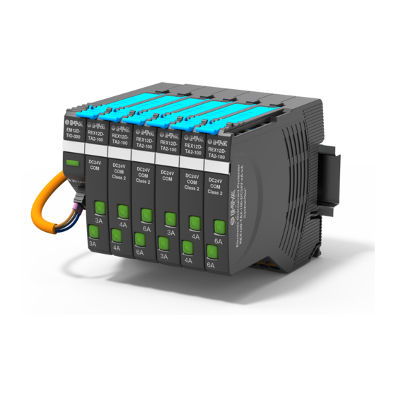
3.1 Design of the entire system Master Port1 EM12D- REX12D- REX12D- REX12D- TIO-xxx TA2-100 TA2-100 TA2-100 DC24V DC24V DC24V 24 V DC/ 10 A DC24V 4230-T110 100-240 V AC fig. 1: System overview The EM12D-TIO intelligent supply module is the centre of the diagnosis and control of the individual channels of the electronic ControlPlex ®... -
Page 9: Dimensions Of The Em12D-Tio Intelligent Supply Module
3.2 Dimensions of the EM12D-TIO intelligent supply module 12,4 connector label e.g. from 3-pole EM12D- Phoenix Contact TIO-xxx ZBF-12 G E R M A N Y LED CE/CM DC24V 40 A LINE +1 snap-on socket for rail EN 60715-35x7.5 fig. 2: EM12D-TIO 3.3 Status indication and terminals EM12D- TIO-xxx... -
Page 10: Connector Socket For The Io Link Master®, Connector Socket X81
Entrance Module EM12D-TIO-000-DC24V-40A max. 16 channels REX12D-T EM12D-T ADDR IO-Link LINE+1 LOAD+ 2.1 (2.2) E-T-A D-90518 ALTDORF Made in Germany • xxxx • xxxxx • x date code Device ID revision status of firmware fig. 5: marking of date code... -
Page 11: Mounting And Installation
4 Mounting and installation 4.1 Mounting of the system The preferred mounting position of the EM12D-TIO is horizontal. fig. 6: Mounting position 4.2 Wiring and connection of the EM12D-TIO intelligent supply module EM12D- TIO-xxx IO link connection X81 COM 0 V terminal DC24V push-in PT 2.5 40 A... -
Page 12: Supply By Means Of Io Link Connector X81 Com
4.2.1 Supply by means of IO link connector X81 COM Voltage ratings: DC 24 V (18 ... 30 V) ® Terminal L+: IO link DC +24 V (line +) Terminal C/Q: Data cable IO link® (COM) Terminal L-: IO link ®... -
Page 13: Operating Modes And Signalling
5 Operating modes and signalling 5.1 Operating mode: (system start) Should the connection between the EM12D-TIO and the When applying the supply voltage, the EM12D-TIO intelligent superordinate IO link master be interrupted and the non-cyclical supply module will be initialised. The device will carry out parameter unfreeze be set, all circuit protectors will be switched implemented programme memory tests and self test routines. -
Page 14: Signalling Of Operating Modes On Em12D-Tio Supply Module
5.6 Signalling of operating modes on supply module EM12D-TIO The different operating modes of the EM12D-TIO are indicated as follows: Operating mode Indication of operating mode IO link communication independent operation blinking green not connected faultless operation green connected critical failure detected not connected uncritical failure detected orange... -
Page 15: Basic Functions Of The Entire System
6 Basic functionalities of the entire system 6.1 Internal cycle time The cycle time via the ELBus ® is 340 ms. During the aforementioned period, the status and the load current of each circuit protector are cyclically transmitted to the EM12D-TIO intelligent supply module. Cyclical Data 16 x 15 ms = 240 ms Non-cyclical Data 100 ms fig. -
Page 16: Types Of Communication
7 Communication types 7.1 SIO mode, group signal at PLC input Commencing with revision F, the SIO mode is available in the supply module. It is possible to connect the EM12D-TIO directly to a PLC input. In this case, it is not the IO link information that is going to be transmitted, but only the group status signal. -
Page 17: Iodd File
7.3 IODD file The IODD file is in the download area of the E-T-A website and can be downloaded there. It is set up according to the regulations of the IO link user organisation (PROFIBUS User Organisation e.V.). Various IODDs are available. -
Page 18: Cyclical I/O Data
8 Cyclical I/O data The IODD file defines the data communication between the IO link master and EM12D-TIO intelligent supply module. In detail these are the status and the load current of the electronic circuit protectors. In addition it is possible to switch the devices on or off or reset them in the event of a failure. - Page 19 parameters byte type range description overload 18 HighByte Word 0xFFFF bit 0 = channel 1 (Channel Overload) 19 LowByte bit 1 = channel 2 bit 2 = channel 3 bit 3 = channel 4 bit 4 = channel 5 bit 5 = channel 6 bit 6 = channel 7 bit 7 = channel 8 bit 8 = channel 9...
- Page 20 parameters byte type range description Hardware Lock 24 HighByte Word 0xFFFF bit 0 = channel 1 (Device Locked Off) 25 LowByte bit 1 = channel 2 bit 2 = channel 3 bit 3 = channel 4 bit 4 = channel 5 bit 5 = channel 6 bit 6 = channel 7 bit 7 = channel 8...
- Page 21 Outputs parameters byte type range description acknowledge channel 0 HighByte Word 0xFFFF bit 0 = channel 1 (Channel 1 to 32 1 LowByte bit 1 = channel 2 (reset)) bit 2 = channel 3 bit 3 = channel 4 bit 4 = channel 5 bit 5 = channel 6 bit 6 = channel 7 bit 7 = channel 8...
-
Page 22: Data Model For Max. 32 Channels
8.2 Data model for max. 32 channels 8.2.1 Data from IO link master to EM12D-TIO (32 channels) Each channel of each electronic circuit protector can be switched on or off or reset via the cyclical data. In addition, status information and measuring values are transmitted. - Page 23 parameters byte type range description overload 4 HHByte Dword 0xFFFFFFFF bit 0 = channel 1 (Channel Overload) 5 HByte bit 1 = channel 2 6 LByte bit 2 = channel 3 7 LLByte bit 3 = channel 4 bit 4 = channel 5 bit 5 = channel 6 bit 6 = channel 7 bit 7 = channel 8...
- Page 24 parameters byte type range description limit value 12 HHByte Dword 0xFFFFFFFF bit 0 = channel 1 (Channel Threshold) 13 HByte bit 1 = channel 2 14 LByte bit 2 = channel 3 15 LLByte bit 3 = channel 4 bit 4 = channel 5 bit 5 = channel 6 bit 6 = channel 7 bit 7 = channel 8...
- Page 25 parameters byte type range description system width byte 0xFF bit 0 = low voltage information bit 1 = permanently ON (for diagnostic purposes) (Overall Status) bit 2 = EL-Bus error (from index I) bit 3 = reserve bit 4 = reserve bit 5 = reserve bit 6 = reserve bit 7 = reserve...
- Page 26 parameters byte type range description switch channel ON/ 4 HHByte Dword 0xFFFFFFFF bit 0 = channel 1 5 HByte bit 1 = channel 2 6 LByte bit 2 = channel 3 (Channel 1 to 32) 7 LLByte bit 3 = channel 4 (on/off)) bit 4 = channel 5 bit 5 = channel 6...
-
Page 27: Non-Cyclical I/O Data
9 Non-cyclical I/O data The non-cyclical data communication allows the exchange of more information between the control unit and the individual circuit protectors than via the limited cyclical range. Depending on the selected index, a varying number of data bytes are exchanged in the non-cyclical data traffic. -
Page 28: Identical Data Model For Max. 16 Channels And 32 Channels
9.1 Identical data model for max. 16 channels and 32 channels 9.1.1 System commands IO link EM12D-TIO (index 2) One byte is transmitted to the master, which carries out the following functions depending on its value. 9.1.1.1 Store adjustments in master (data storage) If the value 5 is transmitted to the master, all parameters will be saved in the IO link master and, depending on the setting of the master, can be restored automatically after exchange of the device. -
Page 29: Extended Device Status
9.1.2.7 Extended Device Status The device supports the IO link property »Extended Device Status« (index 37). Please also see »IOL-Interface-Spec 10002 Version 1.1.2« of 13.07.2013. The data length is 64x3 byte. Below please find the table B14 in detail - Detailed Device Status on page 227 of the spec. sub-index [dec.] object name data type... -
Page 30: Data Model For Max. 16 Channels
9.2 Data model for max. 16 channels 9.2.1 Configuration data of the EM12D-TIO intelligent supply module 9.2.1.1 Internal cycle time (index 198) When reading index 198, one byte is returned. The internal cycle time depends on the number of connected circuit breakers. value range: 100 ms –... -
Page 31: Configuration Data Of The Em12D-Tio Intelligent Supply Module (Index 200)
9.2.1.3 Configuration data of the EM12D-TIO intelligent supply module (index 200) When reading index 200, one byte is returned, this index can also be edited. This byte holds the configuration data of the EM12D-TIO intelligent supply module. Evaluation is bit-wise. value range: 0 –... -
Page 32: Diagnostic Information Of The Em12D-Tio Intelligent Supply Module (Index 300)
9.2.2 Diagnostic information of the EM12D-TIO intelligent supply module (index 300) When reading index 300, two bytes are returned, the 2 bytes input data contain the following global errors and diagnostic messages. Evaluation is bit-wise. value range: 0 – 65535 data length: 1 word (unsigned integer) byte [0]... -
Page 33: Parameters Of Channel For 16 Channels
9.2.3 Parameters of channel for 16 channels When reading the index 101 – 116, two bytes each are returned (with 16 channels). 9.2.3.1 Current rating for 16 channels The parameter in byte [1] returns the current rating of the channel in Ampere. The edit command of this value will be ignored for devices with fixed current ratings and will be adopted for the adjustable ones. -
Page 34: Diagnostic Information Channel With 16 Channels
9.2.4 Diagnostic information channel with 16 channels When reading the index 301– 316, one byte each is returned. If the channel contains errors, these will be returned here as values between 0 and 255. For the meaning of the values please see the following table. value range: 0 –... -
Page 35: Load Voltage Channel For 16 Channels
9.2.5 Load voltage channel for 16 channels When reading the index 401 – 416, two bytes each are returned (with 16 channels). Byte[1] - byte[2] contain the load voltage of the channel value range: 0 – 65535 data length: 1 word (unsigned integer) byte[1] (LOW) bit 7 bit 6... -
Page 36: Trip Counter For 16 Channels
9.2.6.2 Trip counter for 16 channels Byte [2] contains the number of trippings since the trip counter was last reset. value range: 0 ... 255 data length: 1 byte (unsigned character) byte [2] bit 7 bit 6 bit 5 bit 4 bit 3 bit 2 bit 1... -
Page 37: Device Information Channel For 16 Channels
9.2.8 Device information channel for 16 channels When reading the index 701 – 716, 10 bytes each are returned (with 16 channels). 9.2.8.1 Device type for 16 channels Byte[9] and [10] hold information on the device type of the circuit protector. value range: 0 ... -
Page 38: Software Version For 16 Channels
9.2.8.3 Software version for 16 channels Byte[5] – byte[6] contain the hardware version of the corresponding channel. The software version is made available BCD coded. It is coded as follows: software version = X.Y.Z High Byte (Bit 12 – Bit 15) = 0 High Byte (Bit 8 –... -
Page 39: Statistical Information For 16 Channels
byte[4] (HIGH) bit 27 bit 26 bit 25 bit 24 description 134217728 67108864 33554432 16777216 value byte[4] (HIGH) bit 31 bit 30 bit 29 bit 28 description 2147483648 1073741824 536870912 268435456 value fig. 34: Device information channel: serial number 9.2.9 Statistical information for 16 channels When reading the index 801 –... -
Page 40: Mean Value Current For 16 Channels
9.2.9.3 Mean value current for 16 channels Byte[7] – byte[8] contain the mean current value of the channel since the last reset. value range: 0 ... 65535 data length: 1 word (unsigned integer) byte[7] (LOW) bit 7 bit 6 bit 5 bit 4 bit 3 bit 2... -
Page 41: Mean Value Voltage For 16 Channels
9.2.9.6 Mean value voltage for 16 channels Byte[1]– byte[2] contain the mean voltage value of the channel since the last reset. value range: 0 ... 65535 data length: 1 word (unsigned integer) byte[1] (LOW) bit 7 bit 6 bit 5 bit 4 bit 3 bit 2... -
Page 42: (Plclock Index 199)
byte [1] bit 15 bit 14 bit 13 bit 12 bit 11 bit 10 bit 9 bit 8 description 32768 16384 8192 4096 2048 1024 PLCLock channel 9 PLCLock channel 10 PLCLock channel 11 PLCLock channel 12 PLCLock channel 13 PLCLock channel 14 PLCLock channel 15 PLCLock channel 16... -
Page 43: Configuration Data Of The Em12D-Tio Intelligent Supply Module (Index 200)
9.3.1.2 Configuration data of the EM12D-TIO intelligent supply module (index 200) When reading index 200, one byte is returned, this index can also be described. This byte holds the configuration data of the EM12D-TIO intelligent supply module. Evaluation is bit-wise. value range: 0 –... -
Page 44: Diagnostic Information Of The Em12D-Tio Intelligent Supply Module (Index 300)
9.3.2 Diagnostic information of the EM12D-TIO intelligent supply module (index 300) When reading index 300, two bytes are returned, the 2 bytes input data contain the following global errors and diagnostic messages. Evaluation is bit-wise. value range: 0 – 65535 data length: 1 word (unsigned integer) byte [0]... -
Page 45: Parameters Of Channel For 32 Channels
9.3.3 Parameters of channel for 32 channels When reading the index 101 – 132, two bytes each are returned (with 32 channels). 9.3.3.1 Current rating for 32 channels The parameter in byte [1] returns the current rating of the channel in Ampere. The edit command of this value will be ignored for devices with fixed current ratings and will be adopted for the adjustable ones. -
Page 46: Diagnostic Information Channel For 32 Channels
9.3.4 Diagnostic information channel for 32 channels When reading the index 301 – 332, one byte each is returned. If the channel contains errors, these will be returned here as values between 0 and 255. For the meaning of the values please see the following table. value range: 0 –... -
Page 47: Load Voltage Channel For 32 Channels
9.3.5 Load voltage and load current channel for 32 channels When reading the index 401– 432, four bytes each are returned. Byte [1] - byte [2] contain the load voltage of the channel. value range: 0 – 65535 data length: 1 word (unsigned integer) byte[1] (LOW) bit 7... -
Page 48: Error Memory For 32 Channels
9.3.6.1 Error memory for 32 channels Byte[1] holds the internal error memory of the circuit protector. value range: 0 – 255 data length: 1 byte (unsigned character) byte [1] bit 7 bit 6 bit 5 bit 4 bit 3 bit 2 bit 1 bit 0 description... -
Page 49: Device Information Channel For 32 Channels
9.3.7 Action commands channel for 32 channels One byte is transmitted, which carries out the following functions depending on its value. value range: 115 – 116 data length: 1 byte (unsigned character) byte [1] bit 7 bit 6 bit 5 bit 4 bit 3 bit 2... -
Page 50: Hardware Version For 32 Channels
9.3.8.2 Hardware version for 32 channels Byte[7] – Byte[8] contain the hardware version of the corresponding channel. The hardware version is made available in whole numbers. value range: 0 ... 65535 error: hardware version not available (65535) data length: 1 word (unsigned integer) byte[7] (LOW) bit 7 bit 6... -
Page 51: Serial Number For 32 Channels
9.3.8.4 Serial number for 32 channels Byte[1] – byte[4] contain the serial number of the corresponding channel. value range: 0 ... 4294967295 error: Serial number not available (4294967295) data length: 4 byte (unsigned long) byte[1] (LOW) bit 3 bit 2 bit 1 bit 0 description... -
Page 52: Statistical Information For 32 Channels
9.3.9 Statistical information for 32 channels When reading the index 801– 816, twelve bytes each are returned.. 9.3.9.1 Minimum current for 32 channels Byte[11] – byte[12] contain the lowest current value of the channel since the last reset. value range: 0 ... -
Page 53: Maximum Current For 32 Channels
9.3.9.3 Mean value current for 32 channels Byte[7] – byte[8] contain the mean current value of the channel since the last reset. value range: 0 ... 65535 data length: 1 word (unsigned integer) byte[7] (LOW) bit 7 bit 6 bit 5 bit 4 bit 3 bit 2... -
Page 54: Minimum Voltage For 32 Channels
9.3.9.5 Maximum voltage for 32 channels Byte[3] – byte[4] contain the highest measured voltage of the channel since the last reset. value range: 0 ... 65535 data length: 1 word (unsigned integer) byte[3] (LOW) bit 7 bit 6 bit 5 bit 4 bit 3 bit 2... -
Page 56: Appendix
10 Appendix 10.1 List of pictures Fig. 1: System overview Fig. 2: EM12D-TIO Fig. 3: Status indicators and terminals EM12D-TIO Fig. 4: IO link connection Fig. 5: Manufacturing date code Fig. 6: Mounting attitude Fig. 7: Terminals EM12D-TIO Fig. 8: Connection of IO link connector Fig. -
Page 57: Technical Data
Fig. 50: Diagnosis channel: trip counter Fig. 51: Diagnosis channel: trip reason Fig. 52: Action commands channel Fig. 53: Device information channel: type Fig. 54: Device information channel: hardware version Fig. 55: Device information channel: software version Fig. 56: Device information channel: Serial number Fig. - Page 58 Notes...
- Page 59 Notes...
- Page 60 E-T-A Elektrotechnische Apparate GmbH Industriestraße 2-8 . 90518 Altdorf Bedienungsanleitung/Instruction manual B_EM12D-TIO_REX12D_020620 GERMANY Bestell-Nr./Ref. number Y 312 28701 - Index: e Phone +49 9187 10-0 . Fax +49 9187 10-397 Issue 06/2020 E-mail: info@e-t-a.de . www.e-t-a.de Alle Rechte vorbehalten / All rights reserved...
Need help?
Do you have a question about the ControlPlex EM12D-TIO and is the answer not in the manual?
Questions and answers