Table of Contents
Advertisement
Advertisement
Table of Contents

Subscribe to Our Youtube Channel
Related Manuals for LiteOn EVO 8000 Series

Summary of Contents for LiteOn EVO 8000 Series
-
Page 2: Table Of Contents
Table of Contents Chapter 1│Safety............................. 1 1.1 General Safety ..........................1 1.2 Warning Label……………………………………………………………………………………………………………………….4 1.3 AC Drive Application Precautions ....................5 1.4 Warranty ............................6 Chapter 2│Product ..........................7 2.1 Components of Inverter ....................... 7 2.2 Nameplate ........................... 12 2.3 Model Number Definition ......................13 2.4 Power Ratings .......................... - Page 3 7.4 MODBUS Data List ........................142 APPENDIX UL DESCRIPTION ......................... 156...
-
Page 4: Chapter 1│Safety
The product must be complete, including packaging, instruction and accessories. New or updated information, please refer to the following link: http://www.liteon-ia.com/TW/download.php 1.1.3 Installation Warning Carry the drive by the bottom as carrying by the front cover may cause injury and damage from the main body of the drive falling. - Page 5 A control panel must have cooling fans, air vents and room for ventilation when the drive is installed inside. The mounting surface in contact with the heat sink should be made of metal, which provides good thermal conductivity and prevents flammability ...
- Page 6 1.1.5 Operation Caution Connect the power after completion of wiring and closing the front cover. Opening the front cover when the power is on could cause an electrical shock. Keep other personnel off the equipment when setting the drive fault restart and momentary power loss restart functions.
-
Page 7: Warning Label
The release of breaker on the AC drive primary side could be caused by incorrect wiring, short circuit and damaged drive components. Investigate and remove the problem before reconnecting the breaker. Do not use a megger (insulation resistor) to test the drive control circuit. Failure to comply could cause drive damage. -
Page 8: Ac Drive Application Precautions
1.3 AC Drive Application Precautions 1.3.1 AC Drive Selection 1.3.1.1 Drive Capacity Before driving motors, ensure the motor rated current is lower than the drive rated output. In addition, when a single AC drive is driving more than 1 motor in parallel, make sure the drive capacity is higher than 110% of total motor rated current. -
Page 9: Warranty
1.3.3 General Handling 1.3.3.1 Wiring Connecting power supply to output terminals U/T1, V/T2 and W/T3 will damage the drive. Check all the connections and wiring sequence before turning on the power. Failure to comply could cause drive damage. 1.3.3.2 Maintenance Capacitors in the drive may still be charged for a short time after shutting off the power. -
Page 10: Chapter 2│Product
Chapter 2│Product 2.1 Components of Inverter This section describes the components of inverter. 2.1.1 Cabinet Panel Mounting Frame1 A – Heatsink F – Terminal cover screw K –Terminal cover screw G – Front cover B – Cooling fan L – Keypad C –... - Page 11 Frame2 A – Heatsink K –Terminal cover screw F – Terminal cover screw B – Cooling fan G – Front cover L – Keypad C – Cooling fan guard H – USB port D – Conduit bracket I –Terminal cover E –...
- Page 12 A – Upper protective cover K – Front cover screw F – Robber bushing B – Heatsink L – Terminal cover screw G – Terminal cover screw C – Cooling fan M–Keypad H – Front Cover D – Cooling fan guard I –USB port E –...
- Page 13 Frame5 I Internal circulation fan A Cooling fan iron mesh screw J Front cover B Cooling fan iron frame K Front upper cover screw C Inner circulation fan housing screw L Operating the keyboard cover D Internal circulation fan housing M Operating keyboard cover screws E Cooling fan iron frame screw N Operating keyboard...
- Page 14 Frame6 A Cooling fan iron mesh screw I Internal circulation fan B Cooling fan iron frame J Front cover C Inner circulation fan housing screw K Front upper cover screw D Internal circulation fan housing L Operating the keyboard cover E Cooling fan iron frame screw M Operating keyboard cover screws G Cooling fan...
-
Page 15: Nameplate
2.2 Nameplate Model Number Applicable motor rating Input power supply Output power supply... -
Page 16: Model Number Definition
2.3 Model Number Definition 8000 Version: Keypad Type: Filter: Product Series: S: Standard E: LED □ : No Filter EVO: Lite-On AC Drive C: LCD F: Filter Built-In Series Name Enclosure: 00: IP00 20: IP20 Power Ratings: N□:NEMA□ Voltage Class: 0D2: 0.2kW 21: AC 220V 1Phase 0D4: 0.4kW... -
Page 17: Power Ratings
2.4 Power Ratings 400V 1D5 2D2 3D7 5D5 7D5 011 015 018 022 030 037* 045* 055* 075* 090* 110* Model No. EVO800043S 100 125 150 Max. Motor 0.75 18.5 Capacity 7.2 11.7 15.6 23.4 31.2 40.3 50.7 58.5 78 102 125 150 180 210 Current(A) Rated... -
Page 18: Common Specifications
2.5 Common Specifications Item Specification V/F, V/F pay PG, asynchronous motor/synchronous motor pay PG current vector control, asynchronous motor/synchronous motor Control Method without sense current vector control, asynchronous motor without sense voltage vector control, asynchronous motor/synchronous motor pay PG torque control, position control - Pulse synchronization. Output Frequency 1 to 400 Hz Digital Input: Within ±0.01% of the max. - Page 19 Indoor without corrosive gas/liquid or flammable gas/liquid/oil Area of Use mist/dust Ambient -10℃ to +50℃, -10℃ to +40℃ (NEMA1), below 95% RH without Temperature froze or condensation Storage -20℃ to +60℃ Temperature Altitude Up to 1000 meters Shock 10 to 20 Hz (9.8 m/s2) , 20 to 55 Hz (5.9 m/s2) Enclosure IP20, NEMA1 (with optional NEMA kit) 2 points (AI1: 0 to 10V, -10V to 10V (12 bits);...
-
Page 20: Product Dimensions
2.6 Product Dimensions Frame 1 EVO800043SD75E20, EVO800043S1D5E20, EVO800043S2D2E20 Series Frame Size Φ Φ1 Φ2 EVO8000 130[5.12] 118[4.65] 225[8.85] 210[8.26] 150[5.9] 54[2.12] 5.5[0.22] 5.5[0.22] 22[0.86] 28[1.1] Unit: mm/inch... - Page 21 Frame 2 EVO800043S3D7E20, EVO800043S5D5E20 Series Frame Size Φ Φ1 Φ2 EVO8000 130[5.12] 118[4.65] 250[9.84] 235[9.25] 175[6.88] 64[2.51] 5.2[0.20] 5.5[0.22] 22[0.86] 28[1.1] Unit: mm/inch...
- Page 22 Frame 3 EVO800043S7D5E20, EVO800043S011E20, EVO800043S015E20 Series Frame Size 180[7.09] 162[6.38] 310[2.2] 290.6[11.44] 195[7.68] 89[3.5] EVO8000 Φ Φ1 Φ2 Φ3 8.4[0.33] 8.4[0.33] 22[0.86] 28[1.1] 44[1.73] Unit: mm/inch...
- Page 23 Frame 4 EVO800043S018E20, EVO800043S022E20, EVO800043S030E20 Series Frame Size 240[9.45] 222[8.74] 420[16.53] 395.5[15.57] 235[9.25] 113.7[4.47] EVO8000 Φ Φ1 Φ2 Φ3 8.4[0.33] 8.4[0.33] 22[0.86] 28[1.1] 44[1.73] Unit: mm/inch...
- Page 24 Frame5 Frame Size 310.2[12.213] 270[10.630] 558.7[21.996] 530[20.866] 315[12.402] EVO8000 Φ 11[0.43] 11[0.43] Unit: mm/inch...
- Page 25 Frame6 Frame Size 344[13.543] 260[10.236] 672[26.457] 640[25.197] 350[13.780] EVO8000 Φ 11[0.43] 11[0.43] Unit: mm/inch...
-
Page 26: Filter
2.7 EMC Filter Name Power(KW)(HD) Rated Current(A)(ND) Filter Selection 380~480 V , -15% ~ +10% , 50/60Hz EVO800043S1D5 Schaffner(FN3258-7-45) EVO800043S2D2 Schaffner(FN3258-16-45) EVO800043S3D7 10.7 Schaffner(FN3258-16-45) EVO800043S5D5 PIONEER(PE3200-65-06) EVO800043S7D5 PE3200-35-01 EVO800043S011 PIONEER(PE3200-100-06) EVO800043S015 Schaffner(FN3258-7-45) EVO800043S018 43.2 Schaffner(FN3258-16-45) EVO800043S022 56.8 Schaffner(FN3258-16-45) EVO800043S030 70.1 PIONEER(PE3200-65-06) Note: This table is for reference... -
Page 27: Accessories
Name Model Number Description Copy Unit EVO-Kit-CU Allows parameter uploads/ downloads and comparison Communication EVO-KIT-DON USB to RS485 converter* EVO 8000 Series Name Model Number Description EtherCAT EVO8-Comm-EO Connects AC drive with EtherCAT for remote setting and communication monitoring. card*... - Page 28 2.8.2 Brake resistor selection * 125% Braking torque 10%ED Maximum braking torque limit Motor Total Minimum Maximum Maximum Braking Each drive brake electricity total brake peak torque Equivalent braking Current Resistance Current Value power (kg-m) resistor specification limit (Ω) limit (A) (kW) 0.75 100W/750Ω...
-
Page 29: Chapter 3│Drive Installation
Chapter 3│Drive Installation 3.1 Installation Environment To ensure the optimum drive performance, install the AC drive in a proper environment specified below. Environment Conditions Area of Use Indoors -10°C to +40°C (IP20/NEMA 1 enclosure) -10°C to +50°C (IP00 enclosure) ... -
Page 30: Installation Direction And Spacing
3.2 Installation Direction and Spacing 3.2.1 Installation Direction Install the AC drive upright for better cooling Upright installation Horizontal installation Transverse installation Figure 3.1 Installation Direction 3.2.2 Installation Spacing 3.2.2.1 Single Drive Installation Install the AC drive as illustrated below to ensure the required space for airflow and wiring. A –... - Page 31 3.2.2.2 Side-by-Side Installation Install the AC drives as illustrated below to ensure the required space for airflow and wiring. A – Minimum 50 mm B - Minimum 30 mm C - Minimum 10 mm D - Minimum 150 mm Figure 3.3 Installation Space for Side-by-Side Installation Note: When installing drives of different sizes, align the tops of the drives for easier cooling fan replacement.
-
Page 32: Keypad And Terminal Cover Installation
3.3 Keypad and Terminal Cover Installation It is not necessary to remove the keypad before wiring. You just need to loosen the terminal cover screw and remove the terminal cover. 440V 1 to 30HP model enclosure are non-metal. Loosen terminal cover screw and remove terminal cover for wiring. -
Page 33: Wiring Protection
3.4 Wiring Protection 3.4.1 Drive and Input Cable Protection for Short-Circuit Situations Protect the drive and input power cable by using fuse in case potential short-circuit situations cause overheat. Please refer to the following figure for proper wiring. Motor Input cables Fuse Figure 3.4 Fuse Installation 3.4.2 Motors and Output Cable Protection for Short-Circuit Situations... -
Page 34: The Operator Is Installed In The Electric Control Cabinet
3.5 The operator is installed in the electric control cabinet EVO8000 series operators can be used for external pulling. When pulling out, the operator can be fixed on the electric control cabinet through the communication cable. The locking screw used in the operator is M4 X P0.7, the screw used for locking. - Page 35 3.5.1.2 Keypad pull mode The outer pull of the operator is 10M. Inverter RJ45 cable Cable 电缆接口 通讯电缆 变频器 Keypad 操作器 3.5.1.3 Keypad size Minimum bending radius of 50mm or more...
- Page 36 3.5.2 Install the keypad in the electric control cabinet 3.5.2.1 Installation method cabinet 3.5.2.2 Electrical Control Cabinet Processing Size...
-
Page 37: Chapter 4│Wiring
Chapter 4│Wiring 4.1 Wiring Safety Danger Turn off all the power to the equipment before wiring. Wiring during power on could cause electrical shocks to personnel. Allow only qualified personnel for installation, wiring, repairing and parts replacement. Capacitors in the drive may still be charged for a short time after shutting off the power. Wait for the amount of time specified on the drive before any maintenance. -
Page 38: Main Circuit
4.2 Main Circuit Remove DC+(+1/+2) jumper before installing DC reactor. Ensure the Stall Prevention function is off when using a braking resistor. - Page 39 4.2.1 Main Circuit Termin F1-F4 DC Reactor Braking Resistor (option) (option) MCCB (DC+) R/L 1 U/T 1 S/L 2 V/T 2 T/L 3 W/T 3 Fast Acting Fuse F5-F6 Table 4.2.1 Main Circuit Terminals Terminal Name Terminal Description R/L1, S/L2, T/L3 Power input terminal U/T1, V/T2, W/T3 Power output terminal...
- Page 40 4.2.2 Main Circuit Wiring 4.2.2.1 Power Input Terminal Install a molded case circuit breaker (MCCB) between three phase AC input power and main circuit terminals R/L1, S/L2 and T/L3. A magnetic contactor (MC) in series connection is also suggested so as to shut off the power by drive protection functions. Install a R-C varistor on both ends of the MC.
- Page 41 4.2.2.4 Ground Terminal Use grounding cables of dimensions regulated by electrical equipment standard. Shrink wiring distance to prevent leakage current resulting unstable electrical potential at the terminal distant from grounding terminal. Do not use share the same grounding cable with welding machines or any device requiring large current.
- Page 42 4.2.3 Main Circuit Cable Size and Tightening Torque Select the cables and crimp terminals according to Table 4.2.2. 1. The recommended cable size is based on Normal Duty Mode using 75 °C 600 V vinyl-sheathed cable with ambient temperature tolerance below 40 °C and wiring distance less than 100 m. 2.
- Page 43 4.3 Control Circuit J5 is the port for communication option card. Please refer to the instructions during installation. J3 is the port for PG feedback option card. Such option card may be needed depending on the control method. Please refer to the instructions during installation. ...
- Page 44 DIP switch A2 is used to set the analog input type as voltage or current. DIP switch AM is used to set the analog output type as voltage or current. AC (Analog Common) is the common terminal of analog signal. ...
- Page 45 4.3.1.1 Input Terminals Table 4.3.1.1 Control Circuit Input Terminal Terminal Terminal Type Terminal Name Terminal Description Code Digital input terminal 1 (forward/stop) Digital input terminal 2 (forward/stop) Optocoupler 24 V, 8 mA Digital input terminal 3 (external fault 1) It is set to the Sink mode at the Digital input terminal 4 (fault reset) factory.
- Page 46 4.3.1.2 Output Terminals Table 4.3.1.2 Control Circuit Output Terminals Terminal Terminal Type Terminal Name Terminal Description Code Relay 1 normal open Relay 1 normal closed Relay output Multi-Function Relay 1 common DC 30 V, 3 A Relay Output AC 250 V, 5 A Relay 2 normal open Relay 2 normal closed Photocoupler Output terminal 1 (zero speed)
- Page 47 4.3.2 Control Circuit Wiring The applicable functions in parameter Group E can be assigned to multi-function digital inputs (S1 to S8), multi-function relay outputs (R1, R2), multi-function digital outputs (D1, D2), multi-function analog input (A1, A2) and multi-function analog output (FM, AM). The default settings are listed in Figure 4.3.1.1 and Figure 4.3.1.2.
- Page 48 4.3.2.1 Multi-Function Digital Input Wiring Diagram...
- Page 49 4.3.2.2 Pulse input wiring diagram...
- Page 50 4.3.3 Control Circuit Cable Size and Tightening Torque Select the cable according to Table 4.3.3.1. Use crimp ferrules on the cable ends for simpler and more reliable wiring. Table 4.3.3.1 Cable Size and Tightening Torque Tightening Bare Cable Ferrule-Type Terminal Screw Torque Cable...
-
Page 51: I/O Connections
4.4 I/O Connections 4.4.1 Sink and Source Mode Selection Use the Sink/Source switch on the control board to set the multi-function digital input contacts S1 to S8 to Sink or Source mode. Default: Sink mode F1-F4 Source Sink F5-F6 Figure 4.4.1 Sink/Source DIP Switch... - Page 52 4.4.2 Terminal A2 Voltage/Current Input Selection Select voltage or current input at terminal A2 To select current as the input type, set DIP switch A2 to I and set parameter E3-06 to 0 (0 to 20 mA) or 1 (4 to 20 mA). ...
- Page 53 Table 4.4.1 DIP Switch A2 Settings (Terminal A2) Setting Description Voltage input (0 to 10 V or 0 to 5 V) Current input (4 to 20 mA or 0 to 20 mA) (default) Table 4.4.2 Parameter E3-06 Parameter Name Description Setting Range Default Selects the signal level for terminal A2.
- Page 54 F5-F6 Figure 4.4.3 DIP Switch AM Table 4.4.3 DIP Switch AM Setting (Terminal AM) Setting Description Voltage output (0 to 10 V) Current output (4 to 20 mA or 0 to 20 mA) (default) Table 4.4.4 Parameter 4-04 Setting Parameter Name Description Default Range...
- Page 55 F1-F4 F5-F6 Figure 4.4.4 DIP Switch RS-485 Termination Resistor...
-
Page 56: Connection To Pc
4.5 Connection to PC The drive is equipped with a USB port. The drive can connect to a PC through USB cable to manage parameter settings using LiteOn PC software. Note: When USB connection is detected, the communication will be automatically switched from RS485 to USB, and return to RS-485 when USB is disconnected. -
Page 57: Wiring Checklist
4.6 Wiring Checklist Table 4.6 Wiring Checklist □ Page Item Power Supply Voltage and Output Voltage □ 1 Power supply voltage is within the voltage range of specified drive input. □ 2 The motor voltage matches the drive output specifications. □... -
Page 58: Chapter 5│Keypad And Parameters
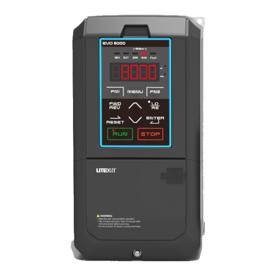
Use the keypad to enter RUN and STOP commands, display data, fault, alarm and set parameters. The keypad of EVO 8000 series can be removed and connected to the drive using an extension cable. The remote keypad can be mounted on control panels with screws thread M4 X P0.7 and the screw length longer than the thickness of panel door. - Page 59 Table 5.1.1 Keypad Keys and Displays Display Name Function FN1 Key User-defined function key for Quick Setting Mode FWD/REV Key Forward/reverse selection Moves the cursor to the right RESET Key Resets the drive to clear a fault situation RUN Key Runs the drive ...
- Page 60 Modbus RUN Light Refer to Table 5.1.2.2 Modbus ERR Light Refer to Table 5.1.2.2 EXT Light Refer to Table 5.1.2.2 REV Light Refer to Table 5.1.2.2...
- Page 61 5.2.1 Keypad Display 5.1.2.1 LED Display Table 5.1.2.1 LED Display Number Number Number Number LED Display LED Display LED Display LED Display /Letter /Letter /Letter /Letter...
- Page 62 5.1.2.2 LED Indication Table 5.1.2.2 LED Indication Indicator Light Blinking Drive in deceleration Output frequency below Drive in operation Drive not in operation the minimum frequency Control from Local Control from Remote Displaying output speed Nil Displaying output frequency Fault operation Normal operation...
- Page 63 ( 1 sec ) MENU ENTER ENTER ENTER MENU MENU MENU UP/DOWN/RESET UP/DOWN/RESET UP/DOWN/RESET B. Quick setting mode: User must assign the function to the FN1 key in advance so as to quickly set the parameter by pressing FN1 key. C.
- Page 64 U1-03 (Output Current) UP/DOWN U1-06 ( Main Circuit DC Voltage UP/DOWN U1-05 (Output Voltage) UP/DOWN U1-04 (Motor Speed) UP/DOWN AI1 (Percentage) UP/DOWN AI2 (Percentage) D. During-operation setting mode: Drive frequency is adjustable during operation in Local mode...
-
Page 65: Parameter List
5.2 Parameter List Parameter Name Description Setting Range Group A, Initialization A1: Basic Settings A1-00 Retain Selects access level ( edit /view) 0: View Only Access to only parameter A1-01 Default∶ 2 Access Level 1: User-Defined Parameter Access A1-01 <4> Min.: 0 Selection Access to only parameter A1-01 and A2-00 to... - Page 66 Parameter Name Description Setting Range 3546: Resets 3-Wire Sequence / 50Hz / 460V 3548: Resets 3-Wire Sequence / 50Hz / 480V 3638: Resets 3-Wire Sequence / 60Hz / 380V 3641: Resets 3-Wire Sequence / 60Hz / 415V 3644: Resets 3-Wire Sequence / 60Hz / 440V 3646: Resets 3-Wire Sequence / 60Hz / 460V 3646: Resets 3-Wire Sequence / 60Hz / 480V 3648: Resets 3-Wire Sequence / 60Hz / 480V...
- Page 67 Parameter Name Description Setting Range A2-12 E2-01 Relay2function selection A2-13 E3-00 Analog A1 input signal A2-14 E3-01 Analog A1 function A2-15 E3-06 Analog A1 function A2-16 E3-07 Analog A2 function User-Defined Saves the most recently edited parameters. Default: 0 A2-32 Parameter 0: Do not save list of recently edited parameters Range: 0, 1...
- Page 68 Parameter Name Description Setting Range Action after Switch If a Run command at the new source is active, the Min.: 0 drive will not start or the drive will stop operation Max.: 1 if it was running when switching from the old source to the new source.
- Page 69 Parameter Name Description Setting Range power up 1∶ Accept Drive accepts an active run command at power up and runs the motor immediately. b1-11 Retain Allow LO/RE switching Default∶ 0 b1-12 0: Invalid selection during Min.: 0 <7> 1: Valid operation Max.: 1 b2: DC Braking...
- Page 70 Parameter Name Description Setting Range <9> time voltage to the set V/F curve voltage during speed Min.: 0.3 s search Max.: 5.0 s b3-03 Retain Set the deceleration time in the speed finding Default∶ 2.0 s b3-04 Speed search action (the time until the highest output Min.: 0.1 s <9>...
- Page 71 Parameter Name Description Setting Range pause function) and b5-29/b5-30 (PID wake function) are valid. 6: PID control is valid (frequency command + PID output, D control for feedback value method Default∶ 1.00 Proportional Gain b5-01 <4> Sets the P gain for PID input. Min.: 0.00 Setting (P) Max.: 25.00...
- Page 72 Parameter Name Description Setting Range 2 ∶ Feedback Low /High Fault A fault will cause the drive to stop the motor. 3 ∶ Multi-Function Output only when PID is Disabled Same action as b5-11=0. 4 ∶ Feedback Low /High Alarm (detection disabled when PID is disabled) 5 ∶...
- Page 73 Parameter Name Description Setting Range <7> limit output of the PID control being lower than the Min.: -100.0% specified value. The d1-02 (the highest output Max.: 100.0% frequency) is set to 100% in %. The d1-02 (the highest output frequency) is set to 100% in %.
- Page 74 Parameter Name Description Setting Range value Max.: <5> Default: 0.0 s b5-30 PID wake-up action Delay the PID action value time setting Min.:0.0 s <9> delay time Max.: 25.5 s When b5-00 = 3, 4, 6 (PID and frequency command superimposed), Adjust the baseline value of b5-05 Default: 0 b5-31...
- Page 75 Parameter Name Description Setting Range Max.: 600.00 % In the position control mode, set the position control function responsiveness. Sets the output width of the zero servo end signal. Set the allowable position deviation amount Default∶ 12 pulse Zero servo end (deviation) at the zero servo start position.
- Page 76 Parameter Name Description Setting Range Deceleration Time 3 Sets the time that the drive decelerates from the C1-05 <4> (Deceleration Time maximum output to 0Hz. 1 for Motor 2) Acceleration Time 4 Sets the time that the drive accelerates from 0Hz C1-06 <4>...
- Page 77 Parameter Name Description Setting Range Default∶ 0.50 Motor 2 Torque Sets the gain for the motor 2 Torque C3-01<4> Min.: 0.00 Compensation Gain compensation Max.: 2.50 Torque Default∶ 2ms C3-02 <4> Compensation Sets the Torque compensation primary delay time. Min.: 0 ms Primary Delay Time Max.:10000 ms Torque...
- Page 78 Parameter Name Description Setting Range reduced the influence of noise interference; the Max.: 1.000 s larger the gain, the higher the filtering degree, but the speed response will also be slower. Default∶ Determined by ASR Primary Delay Sets the primary delay time when the torque A1-02 C4-05 Time...
- Page 79 Parameter Name Description Setting Range Default∶ 0 Speed I-P controller C4-24 Min.: 0 scaling Max.: 1.00 C5: Slip Compensation Default: Determined by Slip Compensation Sets the slip compensation gain to improve the A1-02 C5-00 <4> Gain speed accuracy for heavy loads. Min.: 0.00 Max.: 2.50 Sets the slip compensation primary delay time to...
- Page 80 Parameter Name Description Setting Range Sets the switching frequency of the drive output transistors. Adjust this setting to reduce audible noise and leakage current. Default: Determined by Carrier Frequency 2: 2.0 kHz A1-02 and o2-03. C6-00 Selection 4: 4.0 kHz 8: 8.0 kHz Range: 2 to 16 12: 12.0 kHz...
- Page 81 Parameter Name Description Setting Range To use speed commands for each multi-step Command 1 Min.: 5.00 Hz speed, set E1-□□ to 5, 6, 7 and 8 (multi-step Min.: 0.00 speed command 1, 2, 3, 4). Sets E1-□□ to 9 for Jog Max.: <5>...
- Page 82 Parameter Name Description Setting Range Max.: <5> Default: 50.00Hz Frequency L1-14 <4> Min.: 0.00Hz Command 15 Max.: <5> Default: 50.00Hz Frequency L1-15 <4> Min.: 0.00Hz Command 16 Max.: <5> Default: 6.00 Hz Jog Frequency L1-16 <4> Sets the Jog frequency command. Min.: 0.00Hz Command Max.: <5>...
- Page 83 Parameter Name Description Setting Range 2 ∶ Accept the Up/Down frequency at stop Frequency Default:0.00 Hz Sets the bias used to add to or subtract from the L4-01 <4> Command Bias Min.: 0.00 Hz frequency command by Up/Down 2. (Up/Down 2) Max.: 99.99 Hz Sets the acceleration/deceleration times to Frequency...
- Page 84 Parameter Name Description Setting Range speed reaching the speed limit, increase the set value. Proportional gain Default ∶ 1.00 adjustment factor Set the override of the current controller L5-07 Min.∶ 0.00 for current control proportional gain, please try to avoid changing it. Max.∶...
- Page 85 Parameter Name Description Setting Range from the frequency command. Max.: 100.0% Select the offset frequency in E1-□□= 53, 54 and 55 (Offset Frequency 1 to 3). Group d, Motor Parameters d1: V/F Characteristics Default: Defined by Sets the input voltage of the drive. Input Voltage A1-03 d1-00...
- Page 86 Parameter Name Description Setting Range Default: <1> Middle Output d1-06 Min.: 0.0 Hz Frequency Max.: Defined by d1-02 Default: <1> Middle Output d1-07 Min.: 0.0 V Frequency Voltage Max.: 255.0 V <3> Default: <1> Minimum Output d1-08 Min.: 0.0 Hz Frequency Max.: Defined by d1-02 Default: <1>...
- Page 87 Parameter Name Description Setting Range Motor 2 Minimum Default: <1> d1-20 Output Frequency Min.: 0.0 V Voltage Max.: 255.0 V <3> Default: 0.0 Motor 2 Middle d1-21 Min.: 0.0 Hz Output Frequency 2 Max.: Defined by d1-13 Motor 2 Middle Default: 0.0 V d1-22 Output Frequency...
- Page 88 Parameter Name Description Setting Range Current automatically during Auto-Tuning. Min.: 0.00 A Max.: d2-00 (excluding d2-00) Default: 4 Number of Motor Sets the number of motor poles. This will be set d2-03 Min.: 2 Poles automatically during Auto-Tuning. Max.: 48 Default: o2-03, A1-06 Motor Line-to-Line Sets the line-to-line resistance.
- Page 89 Parameter Name Description Setting Range Sets the motor 2 voltage drop caused by the Default: o2-03, A1-06 Motor 2 Leakage motor leakage inductance relative to the motor d2-16 Min.: 0.00 mH Inductance rated frequency and current. This will be set Max.:650.00 mH automatically during Auto-Tuning.
- Page 90 Parameter Name Description Setting Range is set. Min.: 0.00 mH Max.: 600.00 mH Sets the induced peak voltage per motor phase in Default: Determined by PM Motor Induction units of 0.1 mV/(rad/s) (electrical angle). Set this o2-03 d3-07 Voltage Constant 1 parameter when driving an IPM motor (SSR1 or Min.: 0.0 mV/(rad/s) (Ke)
- Page 91 Parameter Name Description Setting Range 19∶ Baseblock Command (Normal Open) Max.: 0 ~73 / 100 ~173 20∶ Baseblock Command (Normal Closed) Default : 9 Terminal S7 21: Fast Stop (Normal Open) E1-06 Min.: 0 Function Selection 22: Fast Stop (Normal Closed) Max.: 0 ~73 / 100 ~173 23 to 38 : External Fault 39: Fault Reset...
- Page 92 Parameter Name Description Setting Range Selection 4 : Drive Ready Range: 0 to 49 / 100 to 5 : Uv (Undervoltage) Detection 6 : During Baseblock D1-DC Function Default: 1 7 : Retain E2-02 Selection (Open Range: 0 to 49 / 100 to 8 : Frequency Command Source Collector) 9 : Frequency Command Loss...
- Page 93 Parameter Name Description Setting Range Selects the output unit for the terminal assigned to E2-00 or E2-03=37 for one pulse signal. 0: 0.1 kWh units Default: 0 Watt Hour Output E2-05 1: 1 kWh units Range: 0 to 4 Unit 2: 10 kWh units 3: 100 kWh units 4: 1000 kWh units...
- Page 94 Parameter Name Description Setting Range Default: 100.0 % E3-02 Terminal A1 Input Sets the terminal A1 input gain as a percentage Min.: -999.9 % <4> Gain when inputting 10V Max.: 999.9 % Default: 0.0 % E3-03 Terminal A1 Input Sets the terminal A1 input voltage bias as a Min.: -999.9 % <4>...
- Page 95 Parameter Name Description Setting Range action selection and display ANL 2 : Speed to 0Hz and display ANL 3 : Stop immediately and show ACE Default: 0.05 s Terminal A2 Input Sets the terminal A2 primary delay filter time, E3-11 Min.: 0.00 s Filter Time which can eliminate the interference.
- Page 96 Parameter Name Description Setting Range <4> Monitor Voltage Min.: -999.9 % Bias Max.: 999.9 % 0: 0 to 10 V Terminal AM Signal Default: 0 E4-04 1: 0 to 20 mA Level Selection Range: 0, 1, 2 2: 4 to 20 mA Selects the terminal AM monitor.
- Page 97 Parameter Name Description Setting Range <4> Voltage Bias signal (0Hz) is input to terminal RP. Min.: -100.0 Max.: 100.0 Default: 0.10 s E5-04 Pulse Train Input Sets the pulse train input primary filter time in Min.: 0.00 s <4> Filter Time seconds.
- Page 98 Parameter Name Description Setting Range 3: 9600 bps 4: 19200 bps 5: 38400 bps 6 : 57600 bps 7 : 76800 bps 8 : 115200 bps Selects the communication parity for terminals SG(+) and SG(-) of RS-485 communication. 0: 8, N, 2 (Modbus RTU) 1: 8, N, 1 (Modbus RTU) 2: 8, E, 1 (Modbus RTU) 3: 8, O, 1 (Modbus RTU)
- Page 99 Parameter Name Description Setting Range 1 : General-Purpose Motor (Standard Motor) 2 : Drive Dedicated Motor (Constant Torque Range 1 : 10) 3 : Vector Motor (Constant Torque Range 1 : 100) 4 : Derated Torque PM Motor 5 : Constant Torque PM Motor (Constant Torque Range 1 : 500) Sets 0 (disabled) when using one drive to run more than one motor.
- Page 100 Parameter Name Description Setting Range Default: 0.0 s KEB Deceleration P2-04 Sets the time to decelerate during KEB function. Min.: 0.0 s Time Max.: 6000.0 s Sets the time to reaccelerate from the speed when KEB function was deactivated to the set frequency command (operation frequency before Default: 0.3 s Acceleration Time...
- Page 101 Parameter Name Description Setting Range continues when the output current drops 15% below the value set in P3-01. Stall Prevention Default: 150% Sets the output current level to activate the Stall P3-01 Level during Min.: 0% Prevention function during acceleration. Acceleration Max.: 180% Stall Prevention...
- Page 102 Parameter Name Description Setting Range deceleration OVP action Min.: 0 component Max.: 10.000 P3-14 ~ Retain P3-15 P4: Frequency Detection Default: 30.0 Hz Frequency P4-00 Min.: 0.0 Hz Detection Level Max.: 2000 hz Sets the detection level and width for the multi-function output terminal.
- Page 103 Parameter Name Description Setting Range Interval Time attempts. Min.: 0.5 s Max.: 600.0 s P6: Overtorque/Undertorque Detection Sets the operation when the motor current or torque exceeds the P6-01 level for longer than the time set to P6-02. 0 : Disabled Overtorque/...
- Page 104 Parameter Name Description Setting Range above P6-07 3 : Stop Operation if the Speed (Signed) is above P6-07 4 : Stop Operation if the Speed (Unsigned) is above P6-07 5 : Continue Operation if the Speed (Signed) is below P6-07 6 : Continue Operation if the Speed (Unsigned) is below P6-07 7 : Stop Operation if the Speed (Signed) is below...
- Page 105 Parameter Name Description Setting Range 1 : Enabled when One Phase is Lost 2 : Enabled when Two Phases are Lost Enables or disables the output ground fault Output Ground detection. Default: 0 P7-02 0 ∶ Disabled Fault Detection Range: 0, 1 1 ∶...
- Page 106 Parameter Name Description Setting Range n1: Hunting Prevention 0 ∶ Disabled Hunting Prevention Default: 1 n1-00 1 ∶ Enabled Setting Range: 0, 1 If the motor oscillates during light load, gradually Default: 2.00 n1-01 Hunting Prevention increase this value by units of 0.1. If the motor Min.: 0.00 <4>...
- Page 107 Parameter Name Description Setting Range suppression current (overcurrent) or oL1 (motor overload) and oL2 Min.: 0 value (drive overload) occur, reduce the n3-06 setting. Max.: 150% (The inverter rated current is 100%) Group o, Keypad Function Settings o1: Display Setting 0 : Use units of 0.01 Hz 1 : Use units of 0.01% (100% as maximum output frequency)
- Page 108 Parameter Name Description Setting Range Default: <2> o2-03 Drive Capacity Set this parameter after replacing the terminal Determined by <2> Selection block or drive modules. drive capacity 0 ∶ ENTER Key Required 1 ∶ ENTER Key Not Required ENTER Key Function Default: 0 o2-04 During Frequency...
- Page 109 Parameter Name Description Setting Range 1 ∶ Motor 1 Default∶ 1 Set details in d1-00 to d1-11, d2-00 to d2-10. t1-00 Motor 1/2 Selection Min.: 1 2 ∶ Motor 2 Max.: 2 Set details in d1-12 to d1-22, d2-11 to d2-22. 0 ∶...
- Page 110 Parameter Name Description Setting Range Target frequency Default∶ 50Hz Sets the target frequency of rotation during the t1-10 during inertia Min.: 0 inertia estimation estimation Max.: 60Hz Default∶ 50% Rated torque during Sets the rated torque for rotation during the t1-11 Min.: 0 inertia estimation...
- Page 111 Parameter Name Description Setting Range Motor Poles the motor nameplate. Min.: 2 Max.: 48 Default∶ PM Motor Base Sets the PM motor base speed according to the 1750 rpm t2-08 Speed motor nameplate. Min.: 0 rpm Max.: 24000 rpm Default: 0.000Ω PM Motor Rotor Sets the PM motor rotor resistance per phase t2-09...
- Page 112 Parameter Name Description Setting Range Sets the division ratio of pulse output for a PG Default: 1 PG Output Division card. Set X for a ratio of 1/X. F1-02 Min.: 1 Ratio When only A pulse is set, monitor pulse output Max.: 255 will be 1:1 regardless of the setting in F1-02.
- Page 113 Parameter Name Description Setting Range When 0 is set to either F1-14 or F1-15, the ratio will be 1. Sets the number of the gear teeth (ratio) on the machinery side between the motor shaft and PG Default: 1 PG Number of Gear F1-15 encoder.
- Page 114 Parameter Name Description Setting Range station Max.: 127 Select the communication speed of CANopen communication 0 : 1Mbps 1 : 800Kbps CANopen 2 : 500kbps Default: 0 F2-02 communication 3 : 250 kbps Min.: 0 <9> serial transmission 4 : 125 kbps Max.: 8 rate setting 5 : 100 kbps...
- Page 115 Parameter Name Description Setting Range U1-09=C11111111: The following indicate each digit from right to left. 1:Digital Input 1 (S1 enabled ) 1:Digital Input 2 (S2 enabled ) 1:Digital Input 3 (S3 enabled ) 1:Digital Input 4 (S4 enabled ) 1:Digital Input 5 (S5 enabled ) 1:Digital Input 6 (S6 enabled ) 1:Digital Input 7 (S7 enabled ) 1:Digital Input 8 (S8 enabled )
- Page 116 Parameter Name Description Setting Range U1-19 Communication card Display communication card software version <9> software version information U2: Fault Information U2-00 Current Fault Displays the current fault. U2-01 1 Most Recent Fault Displays the first most recent fault. U2-02 2 Most Recent Fault Displays the second most recent fault.
- Page 117 Parameter Name Description Setting Range <7> time when the first "first failure occurred" occurred pre-fault occurred Accumulated running Shows the cumulative running time when the "first U2-18 time before the first failure occurred" occurred failure Frequency Command Displays the frequency command at the second U2-19 at 2 Most Recent...
- Page 118 Parameter Name Description Setting Range operation time before pre-failure" occurred the second failure U2-33 Current Alarm Displays the current alarm. U2-34 1 Most Recent Alarm Displays the first most recent alarm. Most Recent U2-35 Displays the second most recent alarm. Alarm Most Recent U2-36...
- Page 119 Parameter Name Description Setting Range U3-09: 12345MWh Display the output power of the inverter on the monitor. U3-09 5 digits of kWh Displayed separately according to the high and low 0.1kWh <7> (cumulative power) bits (display example) The monitor at 12345678.9kWh is displayed as: U3-08: 678.9kWh U3-09: 12345MWh U3-10 Peak Hold Current...
- Page 120 Parameter Name Description Setting Range Estimate (oL2) accumulator. An oL2 will be triggered when reaching 100%. U4: PID Monitors Displays the PID feedback value as a percentage of U4-00 PID Feedback 0.01% the maximum output frequency. Displays the PID input value as a percentage of the U4-01 PID Input 0.01% maximum output frequency.
- Page 121 <1> The factory setting differs depending on the inverter capacity selection, control mode selection, and ND/HD selection settings. <2> Please refer to the user manual http://www.liteon-ia.com/CHT/download.php <3> The 440V model needs to be multiplied by 2. <4> Parameters that can be set when the inverter is running.
-
Page 122: Chapter 6│Troubleshooting
Chapter 6│Troubleshooting 6.1 Alarm and Fault Displays Table 6.1 Alarm and Fault Displays, Causes, and Possible Solutions Keypad Fault Name Cause Possible Solution Display Retain 1. Remove the cause of the external fault then reset the multi-function 1. An external device input. - Page 123 Keypad Fault Name Cause Possible Solution Display FbL will be triggered malfunction replace the board or the drive. while the PID feedback 4. Incorrect feedback input falls below the level circuit set to b5-12 for longer than the time set to b5-13.
- Page 124 Keypad Fault Name Cause Possible Solution Display 1. Install a DC link choke Voltage surge can result from a thyristor convertor and phase advancing capacitor using the same input power supply 1. Drive input power has 2. Check the motor power cable, surge voltage entering relay terminals and motor terminal 2.
- Page 125 Keypad Fault Name Cause Possible Solution Display settings 2. Ensure there is no problem on The current has dropped 2.Malfunction on machinery the machinery side. below the torque side detection level set to P6-01 for longer than the time set to P6-02 Undertorque Detection 2 1.
- Page 126 Keypad Fault Name Cause Possible Solution Display when E1-口口= 40 input terminal (S1to S8) 1. Reduce the load or use a drive of higher rating 1. The load is too heavy 2. Calculate the torque required 2. Deceleration and during acceleration and the inertia acceleration times are too »Take the following steps if the short...
- Page 127 Keypad Fault Name Cause Possible Solution Display input function is set to 21/121, contact input 1. Difference between PGINI PG card initial failure control board and PG card new and old version 1. Confirm that the firmware 2. The communication version is compatible signal is abnormal.
-
Page 128: Fault Detection
6.2 Fault Detection Table 6.2 Fault Displays, Causes, and Possible Solution Keypad Fault Name Cause Possible Solution Display Output power cable is Check and replace output power Ground Fault damaged cable 1. Increase the deceleration time 1. Regenerative energy is settings (C1-01, C1-03, C1-05, flowing from the motor into C1-07) - Page 129 Keypad Fault Name Cause Possible Solution Display specifications 8. Check the wiring of the braking resistor and braking unit »Correct the wiring 9. Tighten the terminal or replace the damaged cable 10. Correct the wiring 11. Separate the PG wiring from the source of the electrical signal interference (drive output cable) 12.
- Page 130 Keypad Fault Name Cause Possible Solution Display 9. Adjust d1-02 to d1-11 (or d1-13 interference causes drive to d1-22 for motor 2) malfunction 10.Check the amount of torque 11. Overexcitation gain is set compensation too high 11. Find out possible solutions to 12.
- Page 131 Keypad Fault Name Cause Possible Solution Display Frequency Option ) 3.Replace the cooling fan 1. Correct the wiring for terminal Motor Overheat 1. Incorrect motor 2. Check the machinery status The temperature temperature input (terminal 3. Check the load, acceleration / signal from motor MT) wiring deceleration time and cycle time...
- Page 132 Keypad Fault Name Cause Possible Solution Display characteristics. showed on the motor nameplate 10. The electrical thermal relay »Set d1-04 (Base Frequency) operates at the wrong level according to the motor nameplate 11. Motor overheated by 8. Set P1-00 (Motor Protection overexcitation operations Function Selection) to 0 (Disabled) 12.
- Page 133 Keypad Fault Name Cause Possible Solution Display oscillation » Set a lower value to C3-00 (Torque Compensation Gain) until the current is decreased and the motor does not stall. 7. Adjust parameters related to Speed Search » Adjust b3-01 (Speed Search Operation Current) 8.
-
Page 134: Steps For Communicating With The Device/Plc/Human Interface
Keypad Fault Name Cause Possible Solution Display set to P6-04 for longer than the time set to P6-05 Mechanical Weakening Detection for Undertorque Undertorque in the conditions Check the condition of mechanical set to P6-06 weakening Undertorque in the conditions set to P6-06 1. - Page 135 Keypad Fault Name Cause Possible Solution Display input power stabilization 4. Check drive input power. If drive input power seems normal but the alarm continues to occur, replace either the entire drive or the control board. Contact the local distributor for more information. 1.Check the errors for wiring then 1.
- Page 136 Keypad Fault Name Cause Possible Solution Display 2. Incorrect PID feedback 2. Correct the wiring wiring 3. Check the sensor 3. Feedback sensor malfunction 1. Incorrect parameter settings 2. Incorrect PID feedback 1. Reset b5-12 and b5-13 PID Feedback Low wiring 2.
- Page 137 Keypad Fault Name Cause Possible Solution Display any other way or has exceed its expected performance life, follow the instruction for replacement 1. Cycle power to the drive » If the problem continues, replace either the entire drive or the power board.
- Page 138 Keypad Fault Name Cause Possible Solution Display incorrect (if the PG card is not installed, the control mode is set to any PG control mode) 1. The communication signal is 1. Confirm that the equipment abnormal. environment is likely to cause 2.
- Page 139 6.3 Operation Errors Table 6.3 Error Displays, Causes, and Possible Solutions Keypad Error Name Cause Possible Solution Display 1. Set the parameters to the proper Parameter Range Parameters are set outside of oPE02 values Setting Error the possible setting range 2.
- Page 140 Keypad Error Name Cause Possible Solution Display 4. L2-01 ≠ 0 when b5-00 = 3 or 4 V/F Data Setting Error Correct the setting in d1-02, d1-04, d1-02, d1-04, d1-06, V/F parameters setting oPE10 d1-06, d1-08 and d1-10 (or d1-13, d1-08, d1-10 (or incorrect d1-15, d1-17, d1-19 and d1-21).
- Page 141 Keypad Error Name Cause Possible Solution Display Motor synchronous speed = 120 base frequency / motor pole count oPE18 Retain...
- Page 142 6.4 Auto-Tuning Fault Detection Table 6.4 Auto-Tuning Codes, Causes, and Possible Solution Keypad Fault Name Cause Possible Solution Display User presses STOP key during TnF00 Auto-Tuning Stop Do not press STOP key during Auto-Tuning Auto-Tuning The line-to-line resistance in Line-to Line Resistance TnF01 Auto-Tuning is negative or limited by Check and correct motor wiring...
-
Page 143: Chapter 7 │ Communication Protocol
Chapter 7 │ Communication Protocol 7.1MODBUS communication specifications MODBUS communication specifications are: Item Spec Interface RS-485 Synchronously asynchronous Communication Baud rate parameters Data length Parity check: even parity / odd parity / no Stop bit Protocol MODBUS Number of Up to 31 units connectable 7.2 Steps for communicating with the device/PLC/human interface 7.2.1 Communication cable connection... -
Page 144: Information Format
■ When wiring for communication, separate the main circuit wiring from other power lines and power lines. The communication wiring uses a mask wire, and the mask wire is covered and connected to the ground terminal of the inverter, and the other end is not connected and subjected to end processing, thereby preventing the malfunction and causing an erroneous operation. - Page 145 7.4 MODBUS Data List The MODBUS data list is as follows. The types of data include command data, monitoring data, and broadcast transmission data. Instruction DATA (can be read and written) Site Definition 2400H Retain Operational order BIT 0 Stop/Run (0: Stop, 1: Run) BIT 1 Forward/reverse (0: forward, 1: reverse)
- Page 146 BIT 1 1: Reverse running BIT 2 1: Zero speed BIT 3 1: malfunction BIT 4 1: caution BIT 5 1: Consistent frequency BIT 6 1: The inverter is ready to run. BIT 7 1: Frequency provided by communication BIT 8 1: Operation provided by communication BIT 9 1: Torque mode...
- Page 147 242D AO1 Input (-1000 correspond -10V, 0 correspond 0V or 4mA, 1000 correspond 10V or 20mA) AO2 Input (-1000 correspond -10V, 0 correspond 0V or 4mA, 1000 correspond 10V or 242EH 20mA) Warning description (2427H) Value Content Value Content Value Content No warning...
- Page 148 communication error) dEV (Motor HPErr feedback deviation) FbH (PID feedback is AnL(Analog too high) (4-20mA) loss) FbL (PID feedback is ES (emergency stop) too low) Fault description (2428H) Value Content Value Content Value Content No error rSv5 opr (LCM) GF (Ground short) rSv6 SEr (Speed search...
- Page 149 oVCH PF (Input phase) PGErr rSv7 LF1 (Output phase ) PGCON EF0 (communication LF2(PM Motor PGOS error) output current imbalance) EF1 (External fault 1) dEV (Motor feedback Retain deviation) EF2 (External fault 2) Retain TNF00 EF3 (External fault 3) Retain TNF01 EF4 (External fault 4) TNF02...
- Page 150 A2-10 0x008A A2-27 0x009B A2-11 0x008B A2-28 0x009C A2-12 0x008C A2-29 0x009D A2-13 0x008D A2-30 0x009E A2-14 0x008E A2-31 0x009F A2-15 0x008F A2-32 0x00A0 A2-16 0x0090 Parameter Address Parameter Address Parameter Address B1-00 0x0100 B2-00 0x0180 B3-00 0x0200 B1-01 0x0101 B2-01 0x0181 B3-01...
- Page 151 B5-13 0x030D B5-14 0x030E B5-15 0x030F B5-16 0x0310 B5-17 0x0311 B5-18 0x0312 B5-19 0x0313 B5-20 0x0314 Parameter Address Parameter Address Parameter Address B7-00 0x0400 B8-00 0x0480 B9-00 0x0500 B7-01 0x0401 B8-01 0x0481 B9-01 0x0501 B7-02 0x0402 B8-02 0x0482 B9-02 0x0502 B8-03 0x0483 B9-03...
- Page 152 C4-02 0x0702 C5-02 0x0782 C6-02 0x0802 C4-03 0x0703 C5-03 0x0783 C6-03 0x0803 C4-04 0x0704 C5-04 0x0784 C4-05 0x0705 C5-05 0x0785 C4-06 0x0706 C5-06 0x0786 C4-07 0x0707 C5-07 0x0787 C4-08 0x0708 C5-08 0x0788 C4-09 0x0709 C5-09 0x0789 C4-10 0x070A C5-10 0x078A C4-11 0x070B C4-12...
- Page 153 L4-01 0x0A01 L5-01 0x0A81 L6-01 0x0B01 L4-02 0x0A02 L5-02 0x0A82 L6-02 0x0B02 L4-03 0x0A03 L5-03 0x0A83 L4-04 0x0A04 L5-04 0x0A84 L5-05 0x0A85 L5-06 0x0A86 Parameter Address Parameter Address Parameter Address D1-00 0x0B80 D2-00 0x0C00 D3-00 0x0C80 D1-01 0x0B81 D2-01 0x0C01 D3-01 0x0C81 D1-02...
- Page 154 Parameter Address Parameter Address Parameter Address E1-00 0x0D00 E2-00 0x0D80 E3-00 0x0E00 E1-01 0x0D01 E2-01 0x0D81 E3-01 0x0E01 E1-02 0x0D02 E2-02 0x0D82 E3-02 0x0E02 E1-03 0x0D03 E2-03 0x0D83 E3-03 0x0E03 E1-04 0x0D04 E2-05 0x0D85 E3-05 0x0E05 E1-05 0x0D05 E2-06 0x0D86 E3-06 0x0E06 E1-06...
- Page 155 P2-06 0x1086 P3-05 0x1105 P2-07 0x1087 P3-06 0x1106 P2-08 0x1088 P3-07 0x1107 P2-09 0x1089 P3-08 0x1108 P2-10 0x108A P3-09 0x1109 P2-11 0x108B P3-10 0x110A P3-11 0x110B P3-12 0x110C P3-13 0x110D P3-14 0x110E P3-15 0x110F Parameter Address Parameter Address Parameter Address P4-00 0x1180 P5-00...
- Page 156 P7-07 0x1307 P7-09 0x1309 P7-10 0x130A P7-11 0x130B P7-12 0x130C P7-13 0x130D Parameter Address Parameter Address Parameter Address N3-00 0x1480 N4-00 0x1500 N6-00 0x1600 N3-01 0x1481 N4-02 0x1502 N6-01 0x1601 N3-02 0x1482 N4-03 0x1503 N6-02 0x1602 N3-03 0x1483 N5-00 0x1580 N6-03 0x1603 N3-04...
- Page 157 T1-08 0x1888 T2-09 0x1909 T1-09 0x1889 T2-10 0x190A T1-12 0x188C T2-11 0x190B T2-12 0x190C T2-13 0x190D T2-14 0x190E T2-15 0x190F T2-16 0x1910 T2-17 0x1911 Parameter Address Parameter Address Parameter Address F1-00 0x1A00 U1-00 0x1D00 U2-00 0x1D80 F1-01 0x1A01 U1-01 0x1D01 U2-01 0x1D81 F1-02...
- Page 158 U2-25 0x1D99 U2-26 0x1D9A U2-27 0x1D9B U2-28 0x1D9C U2-29 0x1D9D U2-30 0x1D9E U2-31 0x1D9F U2-32 0x1DA0 U2-33 0x1DA1 U2-34 0x1DA2 U2-35 0x1DA3 U2-36 0x1DA4 U2-37 0x1DA5 Parameter Address Parameter Address Parameter Address U3-00 0x1E00 U4-00 0x1E80 U5-00 0x1F00 U3-01 0x1E01 U4-01 0x1E81 U5-01...
- Page 159 APPENDIX UL DESCRIPTION 1) “Maximum surrounding air temperature rating of 50ºC for Open Type; 40ºC for UL Type 1” 2) “The drive is suitable for use in a circuit capable of delivering not more than 5,000 rms symmetrical amperes, 480 Volts Maximum.” These devices are only intended to be installed with the following branch circuit fuse.
- Page 160 6) “Solid State motor overload protection level in percent of full-load current (120% FLA for normal duty, 150% FLA for heavy duty).” 7) “Motor overtemperature protection is not provided by the drive.” 8) Type of electrical supply system (“3WYE” or “480Y/277) to which the drive shall be connected. 9) Use Copper Conductors rated 60/75 C.
- Page 161 COURANT NOMINAL DE COURT-CIRCUIT, 5000 A SYMÉTRIQUES EFF., MAXIMUM 480 V. CONVIENT AUX CIRCUITS NON SUSCEPTIBLES DE DE DÉLIVRER PLUS DE 5000 AMPÉRES SYMÉTRIQUES EFF., MAXIMUM 480 V. AVEC UNE PROTECTION PAR DES FUSIBLES CLASSE RK5 DE CALIBRE NOMINAL MAXIMAL DE V, A, VÉRIFIEZ LE TABLEAU SUIVANT.
- Page 162 Class T, rated 600 V ac, 125 A, Interrupting Current EVO800043S022 200 kA Class T, rated 600 V ac, 125 A, Interrupting Current EVO800043S030 200 kA...
- Page 163 Edit Edit Date Date Parameter Parameter A1-00 b1-00 A1-01 b1-01 A1-02 b1-02 A1-03 b1-03 A1-04 b1-04 A1-05 b1-05 A1-06 b1-06 A2-00 b1-07 A2-01 b1-08 A2-02 b1-09 A2-03 b1-10 A2-04 b2-00 A2-05 b2-01 A2-06 b2-02 A2-07 b2-03 A2-08 b2-04 A2-09 b3-00 A2-10 b3-01 A2-11...
- Page 164 Edit Edit Date Date Parameter Parameter b5-16 C4-01 b5-17 C4-02 b5-18 C4-03 b5-19 C4-04 b5-20 C4-05 b5-21 C4-06 b5-22 C4-07 b5-23 C4-08 b5-24 C4-09 b5-25 C4-10 b5-26 C4-11 b5-27 C4-12 b5-28 C4-13 b6-00 C4-14 b6-01 C4-15 b6-02 C4-16 b6-03 C4-17 C1-00 C4-18 C1-01...
- Page 165 Edit Edit Date Date Parameter Parameter L1-03 d1-13 L1-04 d1-14 L1-05 d1-15 L1-06 d1-16 L1-07 d1-17 L1-08 d1-18 L1-09 d1-19 L1-10 d1-20 L1-11 d1-21 L1-12 d1-22 L1-13 d2-00 L1-14 d2-01 L1-15 d2-02 L1-16 d2-03 L2-00 d2-04 L2-01 d2-05 L3-00 d2-06 L3-01 d2-07 L3-02...
- Page 166 Edit Edit Date Date Parameter Parameter d3-08 E5-03 d3-09 E5-04 E1-00 E5-05 E1-01 E5-06 E1-02 E5-07 E1-03 E6-00 E1-04 E6-01 E1-05 E6-02 E1-06 E6-03 E1-07 E6-04 E2-00 E6-05 E2-01 E6-06 E2-02 E6-07 E2-03 E6-08 E2-04 E6-09 E2-05 E6-10 E3-00 E6-11 E3-01 P1-00 E3-02...
- Page 167 Edit Edit Date Date Parameter Parameter P3-06 P7-06 P3-07 P7-07 P3-08 P7-08 P3-09 P7-09 P3-10 P7-10 P3-11 P7-11 P3-12 P7-12 P3-13 P7-13 P3-14 n1-00 P3-15 n1-01 P3-16 n1-02 P4-00 n1-03 P4-01 n6-00 P4-02 n6-01 P4-03 n6-02 P5-00 n6-03 P5-01 n6-04 P5-02 n6-05 P6-00...
- Page 168 Edit Edit Date Date Parameter Parameter o4-08 F1-10 t1-00 F1-11 t1-01 F1-12 t1-02 F1-13 t1-03 F1-14 t1-04 F1-15 t1-05 F1-16 t1-06 F1-17 t1-07 F1-18 t1-08 S1-00 t1-09 S1-01 t1-10 S1-02 t1-11 S1-03 t1-12 S1-04 t2-00 S1-05 t2-02 S1-06 t2-03 S1-07 t2-04 t2-05 t2-06...
- Page 169 22F, 392, Ruey Kung Road, Neihu, Taipei City 114, Taiwan...
Need help?
Do you have a question about the EVO 8000 Series and is the answer not in the manual?
Questions and answers