
Related Manuals for BERNSTEIN HT01


Summary of Contents for BERNSTEIN HT01
- Page 1 DIGITALES THERMOSTAT DIGITAL THERMOSTAT THERMOSTAT NUMÉRIQUE TERMOSTATO DIGITALE MONTAGEANLEITUNG - I / 2018 ASSEMBLY INSTRUCTIONS / NOTICE DE MONTAGE / ISTRUZIONI DI MONTAGGIO...
-
Page 2: Elektrischer Anschluss
HT01 Platzierung des Bodensensors Der Bodensensor sollte in einem zugelassenen nicht leitenden Installationsrohr gemäß EN 61386-1 installiert werden, das in den Boden eingelassen ist. Der Bodensensor sollte in gleichen Abständen zwischen zwei Läufen des Heizelements angeordnet sein, wobei die Spitze mindestens 300 mm von der Außenkante des Heizelements entfernt sein muss. -
Page 3: Technische Daten
HT01 Technische Daten Spannung: AC230V ± 10% 50/60 Hz Leistungsaufnahme: 5W Einstellungsbereich: 5 ~ 30ºC Bodenüberhitzung Schutz: 30 ~ 80°C (werkseitig auf 65°C eingestellt) Schutzgehäuse: IP20 Gehäusematerial: ABS + PC feuerbeständig Zertifizierung: CE Bodensensor: Gummi-Thermoplast NTC 10K Sensor Interner Sensor: NTC 10K Sensoren Auswahl Der Thermostat ist werkseitig auf die Verwendung der Raum- und Bodentemperatursensoren voreingestellt. -
Page 4: Erweiterte Einstellungen
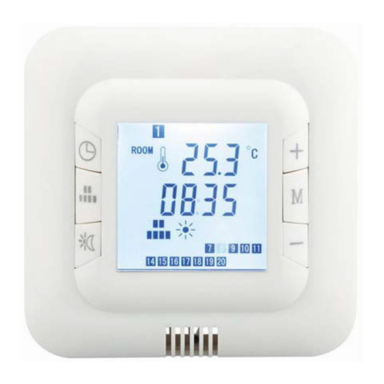
HT01 7 Tage Automatikmodus Um den 7-Tage-Timer-Modus auszuwählen, drücken Sie M, bis auf dem LCD-Bildschirm angezeigt wird. Der Thermostat schaltet dann zwischen Komfort- und Energiesparmodus (Ein / Aus) automatisch gemäß den Datums- und Uhrzeiteinstellungen. Jeder Wochentag kann mit individuellen Einstellungen versehen werden. -
Page 5: Electrical Connection
HT01 Mounting of the floor sensor The floor sensor should be installed within an approved non conductive installation pipe in accordance with EN 61386-1, which is embedded in the floor. The pipe (flexible conduit) should be placed as high as possible in the subfloor. The floor sensor should be located equidistant between two runs of the heating element with the tip at least 300mm away from the outside edge of the heater. -
Page 6: Technical Data
HT01 Technical Data Voltage: AC230V ± 10% 50/60HZ Power Consumption: 5W Setting Range: 5 ~ 30ºC Floor overheating Protection: 30 ~ 80˚C (factory set @ 65˚C) Protective housing: IP20 Housing Material: ABS + PC fire-resistant Certification: CE Floor Sensor: Rubber-Thermoplastic NTC 10K Sensor... -
Page 7: Advanced Settings
HT01 7 Day Automatic mode To select the 7 day timer mode press M until is displayed on the LCD screen. The thermostat will then switch between comfort & energy saving mode (On/Off) automatically according to the day & time settings. Each day of the week can be programmed with individual settings. - Page 8 HT01 Mounting of the floor sensor The floor sensor should be installed within an approved non conductive installation pipe in accordance with EN 61386-1, which is embedded in the floor. The pipe (flexible conduit) should be placed as high as possible in the subfloor. The floor sensor should be located equidistant between two runs of the heating element with the tip at least 300mm away from the outside edge of the heater.
- Page 9 HT01 Technical Data Voltage: AC230V ± 10% 50/60HZ Power Consumption: 5W Setting Range: 5 ~ 30ºC Floor overheating Protection: 30 ~ 80˚C (factory set @ 65˚C) Protective housing: IP20 Housing Material: ABS + PC fire-resistant Certification: CE Floor Sensor: Rubber-Thermoplastic NTC 10K Sensor...
- Page 10 HT01 7 Day Automatic mode To select the 7 day timer mode press M until is displayed on the LCD screen. The thermostat will then switch between comfort & energy saving mode (On/Off) automatically according to the day & time settings. Each day of the week can be programmed with individual settings.
- Page 11 HT01 Mounting of the floor sensor The floor sensor should be installed within an approved non conductive installation pipe in accordance with EN 61386-1, which is embedded in the floor. The pipe (flexible conduit) should be placed as high as possible in the subfloor. The floor sensor should be located equidistant between two runs of the heating element with the tip at least 300mm away from the outside edge of the heater.
- Page 12 HT01 Technical Data Voltage: AC230V ± 10% 50/60HZ Power Consumption: 5W Setting Range: 5 ~ 30ºC Floor overheating Protection: 30 ~ 80˚C (factory set @ 65˚C) Protective housing: IP20 Housing Material: ABS + PC fire-resistant Certification: CE Floor Sensor: Rubber-Thermoplastic NTC 10K Sensor...
- Page 13 HT01 7 Day Automatic mode To select the 7 day timer mode press M until is displayed on the LCD screen. The thermostat will then switch between comfort & energy saving mode (On/Off) automatically according to the day & time settings. Each day of the week can be programmed with individual settings.
- Page 14 HT01 ERKLÄRUNG Die Bedienungsanleitung dient nur als Referenz. Diese Anleitung kann abweichende Angaben enthalten. Die beschriebenen Produkte können jederzeit aktualisiert werden. Die Zeichnungen in dieser Anleitung dienen nur zur Darstellung und haben keinen Anspruch auf Aktualität. STATEMENT This instructions should only be considered as a standard manual. Modifications applied to updated version of the pro- duct might not be mentioned inside this document.
Need help?
Do you have a question about the HT01 and is the answer not in the manual?
Questions and answers