Table of Contents
Advertisement
Quick Links
®
Operating Manual
GageMux
Information in this document is subject to change without notice and does not represent a
commitment on the part of Advanced Systems and Designs, Inc. No part of this manual may
be reproduced or transmitted in any form or by any means, electronic or mechanical,
including photocopying and recording, for any purpose without the express written
permission of ASD.
Operating Manual
®
The ASD and GageMux
logos are registered trademarks of Advanced Systems and Designs,
Inc.
Copyright © Advanced Systems and Designs, Inc., 1984-2004. All rights reserved.
Printed and bound in the United States of America.
Document No. 10040PF
Advanced Systems and Designs, Inc.
2142 Pontiac, Suite 202
Auburn Hills, MI 48326
Phone: (248) 370-9919
Fax: (248) 370-9921
Email: support@spcanywhere.com
Website: http://www.spcanywhere.com
GageMux
®
4 Input Gage Interface
www.spcanywhere.com
ii
(248) 370-9919
Advertisement
Table of Contents

Summary of Contents for ASDQMS GageMux
- Page 1 ASD. Operating Manual ® The ASD and GageMux logos are registered trademarks of Advanced Systems and Designs, Inc. Copyright © Advanced Systems and Designs, Inc., 1984-2004. All rights reserved.
-
Page 2: Table Of Contents
® ® Operating Manual GageMux Operating Manual GageMux Table of Contents Table of Contents..............iv Introduction................1 Features ..................2 Included Items................2 System Requirements ............... 3 ® GageMux Quick Start............... 4 Basic Operation ..............5 Configuration and Setup ............5 Output String Format ............. -
Page 3: Introduction
• RS-232 output. & Designs, Inc. for a complete list of over 300 compatible gages. • ® Daisy chain multiple GageMux units to connect up to 64 digital gages to a single RS-232 serial port. ® The Ga geMux is configured through internal DIP switches or commands from a host computer. -
Page 4: System Requirements
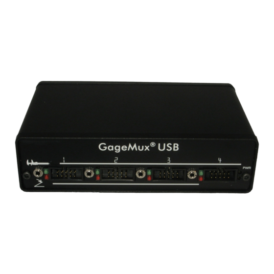
® Before you begin to setup and install the GageMux interface, we Below are diagrams that show the front and rear panels of the GageMux recommend that you first check to see that you have the following components: Port 1... -
Page 5: Basic Operation
In the reading only format, the output string will look like this: ® Connect your gages and foot switches to the GageMux ® Connect the 9 volt DC power supply into the GageMux and plug SRRRRRRR<CR><LF> the power supply into a 110 volt AC outlet. -
Page 6: Foot Switch Operation
Mitutoyo Mux-10 Format “F<CR>” (the letter f followed by a carriage return) is sent. This ® mode is most likely used when the GageMux is under software The Mitutoyo Mux-10 format consists of a string with up to 13 ®... -
Page 7: Normal And Min/Max/Tir Modes
DIPSW1 DIPSW2 DIPSW3 ® For example, in a daisy chained configuration, the first GageMux would be set up so that its ports numbered 1, 2, 3, 4 are assigned to channels 1, 2, ® 3, 4 respectively. The second GageMux... - Page 8 ® ® Operating Manual GageMux Operating Manual GageMux DIPSW1 DIPSW2 • • Switches 1, 2, 3, and 4—Settings for Flow Mode, Foot Switch, Switches 1, 2, 3, 4—Normal or MAX/MIN/TIR Mode Output String Formats, and Baud Rate DIPSW2 DIPSW1 Description...
- Page 9 Operating Manual GageMux DIPSW3 DIPSW3 Continued • Switches 1, 2, 3, 4—Channel Settings for Multiple Daisy ® GageMux Channel Switch Switch Switch Switch ® Chained GageMux Devices Number 33-36 Open Open Open Closed DIPSW3 ® OPEN GageMux Channel Switch Switch...
-
Page 10: Host Commands
1 global. for global foot switch mode). <CR> is a carriage return (Enter). ® XX<CR> Reset the GageMux as if XX<CR> the reset button were Reset the ® pressed. <CR> is a carriage GageMux return (Enter).
Need help?
Do you have a question about the GageMux and is the answer not in the manual?
Questions and answers