Advertisement
Quick Links
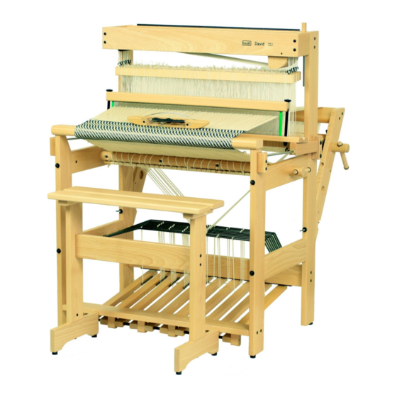
David 2
Instructions for assembly
Assembly tips and information ........................................................................................................ 1
Instructions for assembly ................................................................................................................ 2
Warrantee and contact .................................................................................................................. 17
Version: I_David2_V1_EN
Advertisement

Summary of Contents for Louët David 2
- Page 1 David 2 Instructions for assembly Assembly tips and information ......................1 Instructions for assembly ........................ 2 Warrantee and contact ........................17 Version: I_David2_V1_EN...
- Page 3 The Texsolv system Each shaft of the David 2 is provided with one hundred Texsolv heddles (28 cm long). The ties of these bundles are included and can be used to tie bundles again. A bundle of Texsolv heddles is a continuous line of 100 heddles folded into a zig zag.
-
Page 4: Instructions For Assembly
10 mm and a Pozidrive 2 cross head screwdriver (not a Phillips head). A wrench 13 mm is included with the hardware of the beater. Accessoires The following accessories are available for the David 2: - Bench – height 57 cm (22 3/8”) - Second warp beam with back beam... - Page 5 Parts you will find inside the box that came out first (the reed is packed on top of the box): - foot rail - breast beam - back beam - 2 lease sticks - cloth beam and warp beam - 2 apron bars - 2 upper side rails L+R - 16 warp sticks - shelf...
- Page 6 Open hardware bag 1 The hardware bag contains: - 8 threaded ends m6 X 135 with barrel nut, washer and cap nut. - 4 screws 5 X 50 mm (these screws you will need only for a David 90. Sometimes, for efficiency reasons, they are also included in the hardware bag of the David 70) - wrench 10 mm...
- Page 7 Put a threaded end through the hole in the upright. Slide the rail onto the threaded end and push its wooden dowels into the holes of the upright. Turn the threaded end into the barrel nut, while positioning the barrel nut, if necessary, using a coin or a screwdriver. The lower side rails should be mounted the same way, their nylon bearings facing the middle of the loom.
- Page 8 Insert the lams, one by one, with their ends into the nylon bearings, starting with the rear lam: - Insert one end of the lam into the bearing, while holding the other end of the lam just underneath the side rail. - Now bring that other end to its bearing by bending the lam slightly.
- Page 9 Assemble the treadles onto the foot rail. The screw heads on the treadles should point towards the middle so that the five treadles on the left side are opposite to the five treadles at the right side. Slide two treadles with a nylon bushing in between on each axle.
- Page 10 Open hardware bag 3 The hardware bag contains: 2 threaded ends 6 X 135 each with 2 washers and 2 wing nuts 4 screws 5 X 50 8 screws 4 X 15 2 ratchets 2 screws 4,5 X 17 (round head) 2 screw eyes ...
- Page 11 A spring for each shaft is located at the top of the David. These springs pull up the shafts by cords that run over a wooden disc. A locking pin blocks the moving action of springs, discs, shafts, lams and treadles. This locking pin is inserted into holes in the front and back rail and into holes in the wooden discs.
- Page 12 If you also purchased a brake for the warp beam, find the bracket in the contents of its hardware bag. Attach the bracket onto the warp beam support with the same screws that join the support and the back beam at the side where the end of the warp beam protrudes.
- Page 13 In both uprights at the back of the loom there is a hole in the location where the polyurethane dowels of the back part are inserted. With the two screws 3 X 20 (not the round head 4.5 X 17 ones) you will secure the polyurethane dowels.
- Page 14 Insert the beam handles through the holes in the beams and secure them by rolling the rubber O-ring into the groove around the handles. A spare O-ring is in the hardware bag extra. If you have to assemble a brake for the warp beam, don’t install the handle in the warp beam.
- Page 15 Attach three cords each to the warp beam and the cloth beam with the remaining screws 4x15 mm. Start at one side of the beam with the end of a cord. The other end of that cord has to be fixed together with the end of the next cord in the second hole of the beam etc.
- Page 16 Remove the cap nut and the washer from the threaded end. Insert the threaded end through the hole in the groove of the lower reed holder. The barrel nut fits in the groove and the short end of it should be at the side where the reed will be. Fasten the cap nut with washer onto the thread that protrudes from the bottom side.
- Page 17 Slide the block with the two slots on the carriage bolt. Note that the oval hole faces the front of the loom. The second carriage bolt has to be plugged into the other slot and the other hole. After you've fastened the bolts with washers and wing nuts, mount the second block onto the post at the other side of the loom.
- Page 18 Position the reed and the upper reed holder in between the threaded rods and fasten the assembly with the knurled nuts. Install the breast beam. The metal dowels on the front posts will fit in the holes of the beam. Removing or adding heddles If you want to add heddles or to remove heddles from a shaft, you have to unhook cords from the...
- Page 19 It is handy to insert a knitting needle at the left side through all the cords that the upper shafts bars are connected to. Now when you unhook an upper shaft bar at that side, its cord will stay in place. Use four ties to make a bundle of the heddles before you remove them from a shaft.