Advertisement
Quick Links
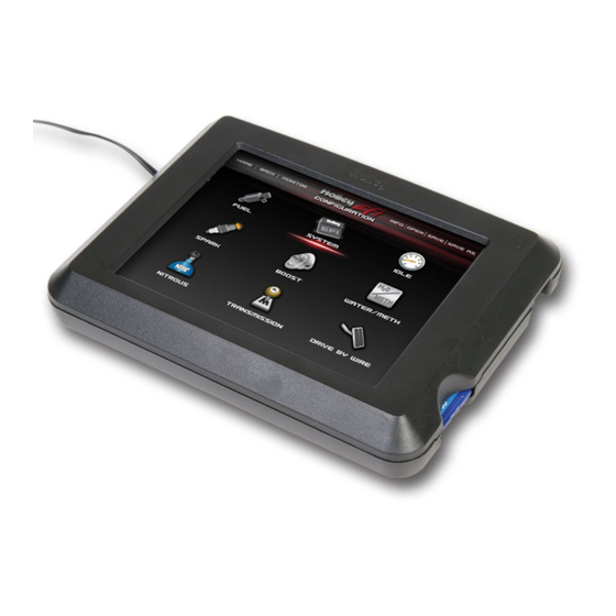
Holley 5.7" Full Color Touch Screen LCD
NOTE: You MUST have ECU firmware version 330 or HIGHER for the Touch Screen to function properly. ECU's with serial numbers
BELOW 700 will NOT have the proper firmware from the factory. You can download the proper firmware from
www.holley.com/TechService/Library.asp
need to use a laptop to upgrade the firmware this first time, future updates can be done via the touch screen. Download the
latest SOFTWARE and FIRMWARE from www.holley.com.
1.0 TSLCD Overview:
The Holley 5.7" Touch Screen LCD is designed specifically for use with Holley Avenger, HP, and Dominator EFI systems. It contains
separate software applications for tuning, gauge displays, and updating ECU firmware.
The Holley 5.7" Touch Screen LCD allows for tuning without the need for a laptop computer in the vehicle.
What the Touch Screen allows you to do in regards to tuning:
Perform real-time tuning of all "tuning" parameters
Enable and Disable certain inputs and output that have previously been enabled and pin-mapped in the calibration.
Download internal ECU data logs to the SD memory card
What the Touch Screen does not allow you to do in regards to tuning and setup:
Perform initial calibration setup of engine and ignition parameters
Enable configure inputs and outputs
Any modifications or setup to the "Inputs/Outputs" ICF.
These functions must be performed on a laptop or desktop computer. This initial setup can downloaded to the ECU via a laptop
computer, or can be downloaded via the Touch Screen on the SD memory card. Using the SD card allows the initial setup to be
performed on a desktop computer, copied to the SD card, then installed via the Touch Screen, eliminating any need for a "laptop"
computer.
2.0 Installation
The touch screen can be flush-mounted into a dash, or installed on a mounting base/bracket. There are 8 threaded attachment points
in the back of the touch screen. These are a 10-24 thread. When installing it, make sure the fasteners used don't bottom out in the
touch screen. If they do, and you over-tighten them, damage will result. Eight 10-24 fasteners are included for mounting purposes.
Depending on how things are mounted, you may need different fasteners. The mounting pattern used is an industry standard mounting
P/N 553-103
. Towards the middle of the page you will find downloads for "Holley EFI". You will
Advertisement

Summary of Contents for Holley EFI 553-103
- Page 1 SOFTWARE and FIRMWARE from www.holley.com. 1.0 TSLCD Overview: The Holley 5.7” Touch Screen LCD is designed specifically for use with Holley Avenger, HP, and Dominator EFI systems. It contains separate software applications for tuning, gauge displays, and updating ECU firmware.
- Page 2 pattern that fits off-the-shelf mounts for most GPS’s, fish finders, and other brackets. The center 4 positions are a “Rectangular AMPS” pattern (30mm x 38mm). The outside four positions are a 140mm x 32mm pattern. The touch screen is not weather resistant and must be installed in a dry environment. Mounting in Race Cars –...
-
Page 3: Sd Memory Card
12 foot extension – Part Number 15644NOS NOTE: Do NOT use a Holley Avenger Handheld controller in conjunction with the touch screen LCD. Use only one or the other. Do NOT have both connected to the CANbus wiring at the same time. -
Page 4: Configuration Application
“Help” Screen – There is help information for every screen within the touch screen. To access it for a specific screen, click once on the title of the screen (directly below the “Holley EFI” in the top/middle of the screen). - Page 5 At the top left of the Screen you see the following: Home – Moves to the main home screen at any time. Back – Moves to the previous screen. NOTE: The “Home” and “Back” buttons are the primary navigation methods. Monitor –...
- Page 6 PC software. Each screen throughout the touch screen has tuning information however, which can be accessed by clicking once on the title of the screen, just below the “Holley EFI” in the top center. Some things that are unique to the...
- Page 7 Figure 10 6.2 Editing 31x31 screens: Due to the size of the screen, the 31x31 fuel or ignition timing tables can’t be shown on one view. There are some very helpful tools that allow for quick changes to these views however. The Base Fuel table is shown below. In this view, you can see the lowermost, left area.
- Page 8 If you click once on the “up/down arrows” on the right of the entry, it will bring up a numeric increment window (Figure 14). If you click TWICE on the number, it will bring up a keypad (Figure 15). Figure 14 Figure 15 To change the values on any table, select the values you want to change (touch and drag over an area as shown in Figure 16).
- Page 9 6.4 Graph Editing To edit a graphical table, you can do the following: Drag points on the graph up or down (Figure 18). Click twice on the numeric value to bring up the calculator (Figure 19). NOTE: the number you change may not reflect your edit until you refresh the screen or move off the value.
- Page 10 8.0 Data Log Figure 22 Setup – Configures the internal ECU data logger (Figure 23). See the help instructions within the touch screen or PC software on proper configuration. It is advised to use slower sampling rates unless needed to minimize file sizes and reduce download times (for basic logging, 5-10 samples per second is adequate.
-
Page 11: View Selection
9.0 Gauge Application 9.1 Overview The gauge application offers several different styles of gauges and numeric readouts. They can be used to completely replace conventional gauges or supplement them as needed. There are different types of gauges and views that all can be custom configured. User programmable caution and warning limits can be assigned to every channel. - Page 12 Figure 27 Digital Gauges – Modern looking digital bar tachometer and readouts. There are two screens that can be configured. These readouts have a limited amount of channels that can be configured. Figure 28 Bar Tachometer – Large tachometer readout display. Figure 29 Switch Panel –...
- Page 13 Figure 30 Touch Screen Switches may be used as "enable/input" from software created I/O (for example nitrous enable) or from a user defined Inputs from the I/O ICF. These switches may also be used to trigger an output once the desired Input has been created. Note** A switched output used in conjunction with a sensor input **both switch and sensor input must be enabled** for output to trigger.
- Page 14 If the channel you want to edit is not available on any of the “Needle/Data” views (there are four of them), then you must remove one of the existing channels and add the one you desire. To do this, simply click on the channel you want to replace. This will bring up the “Data Monitor Set-Up Screen”...
Need help?
Do you have a question about the EFI 553-103 and is the answer not in the manual?
Questions and answers