Table of Contents
Advertisement
Quick Links
Advertisement
Table of Contents

Summary of Contents for Balluf SMARTCAMERA BVS SC 1280Z00-07-000 Series
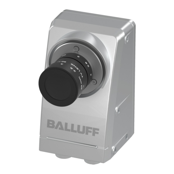
- Page 1 BVS SC-_1280Z00-07-000 SMARTCAMERA IO User's manual English...
- Page 2 www.balluff.com...
-
Page 3: Table Of Contents
BVS SC-_1280Z00-70-000 SMARTCAMERA IO TABLE OF CONTENTS USER INSTRUCTIONS ......................... 3 Introduction ..............................3 Typographical conventions .........................4 2.2.1 Bulleted Lists ............................4 2.2.2 Actions ..............................4 2.2.3 Numbers ..............................4 2.2.4 Parameters ...............................4 2.2.5 Directory paths ............................4 2.2.6 ASCII code ...............................4 2.2.7 Symbols ..............................4 Abbreviations ..............................5 Copyright ...............................6 Legal requirements ............................6... - Page 4 BVS SC-_1280Z00-70-000 SMARTCAMERA IO TABLE OF CONTENTS STARTUP ............................ 32 Updating software ............................32 Network topologies ............................ 34 System settings ............................35 Selecting the communication interface for the process data ............... 35 Network settings / LAN interface ......................36 6.5.1 Locating the camera in the network ......................
-
Page 5: User Instructions
BVS SC-_1280Z00-70-000 SMARTCAMERA IO 2 USER INSTRUCTIONS Introduction These operating instructions describe the SMARTCAMERA product from the Balluff Vision Solution BVS SC product family as well as the data interfaces and the startup for an immedi- ate operation. The web-based software interface integrated in the SMARTCAMERA is described in the separate software manual (BVS Cockpit manual). -
Page 6: Typographical Conventions
BVS SC-_1280Z00-70-000 SMARTCAMERA IO 2 USER INSTRUCTIONS Typographical conventions The following conventions are used in this manual: 2.2.1 Bulleted Lists Enumerations are shown as a list with an en-dash. • Entry1 • Entry 2 2.2.2 Actions Action instructions are indicated by a preceding triangle. The result of an action is indicated by an arrow. -
Page 7: Abbreviations
BVS SC-_1280Z00-70-000 SMARTCAMERA IO 2 USER INSTRUCTIONS Abbreviations Balluff Vision Solution CMOS Complementary metal-oxide-semiconductor Discovery and basic Configuration Protocol DHCP Dynamic Host Configuration Protocol Device ID I/O port Digital input and output port EEPROM Electrical Erasable and Programmable ROM Electromagnetic compatibility EtherNet/IP Ethernet Industrial Protocol Federal Communications Commission... -
Page 8: Copyright
BVS SC-_1280Z00-70-000 SMARTCAMERA IO 2 USER INSTRUCTIONS Copyright Copyright © Balluff GmbH, Neuhausen a.d.F., Germany, 2018. All rights reserved. In particu- lar: Right to duplication, modification, dissemination and translation into other languages. Please note that all texts, graphics and images contained in these operating instructions are protected by copyright and other protection laws. -
Page 9: Safety
BVS SC-_1280Z00-70-000 SMARTCAMERA IO 3 SAFETY Intended use The SMARTCAMERA BVS SC is a camera with integrated image analysis for contactless acquisition and examination of objects in industrial environments. The intended use also includes that you have read these operating instructions in their en- tirety and follow all the information –... -
Page 10: Disposal
BVS SC-_1280Z00-70-000 SMARTCAMERA IO 3 SAFETY Only service technicians from Balluff GmbH may repair defective devices. Intervention in the product by the operator is not permitted due to safety reasons. The SMARTCAMERA's hous- ing may not be opened or loosened! WARNING Before maintenance, disconnect the device from the power supply. -
Page 11: Product Description
BVS SC-_1280Z00-70-000 SMARTCAMERA IO 4 PRODUCT DESCRIPTION The Balluff SMARTCAMERA BVS SC is a camera for the acquisition and analysis of black- and white and color images. Application areas are optical identifications of codes and plain text, inspections for quality assurance and the measurement of objects. The camera can also be used in robot environments. -
Page 12: Scope Of Delivery
BVS SC-_1280Z00-70-000 SMARTCAMERA IO 4 PRODUCT DESCRIPTION Scope of delivery Included in the scope of delivery • SMARTCAMERA BVS SC • Filter (mounted): with monochrome sensor: protection glass with color sensor: IR-Cut • 2 × cap M12 • Safety Precautions •... -
Page 13: Assembly
BVS SC-_1280Z00-70-000 SMARTCAMERA IO 4 PRODUCT DESCRIPTION NOTE Visit www.balluff.com for more information on available software and accessories. 4.2.1 Assembly The camera features 12 internal threads for installation at the location of use. Four threads each at the rear, the left and the right. This ensures secure and reliable mounting. The fol- lowing drawings describe the exact position of all mounting holes. - Page 14 BVS SC-_1280Z00-70-000 SMARTCAMERA IO 4 PRODUCT DESCRIPTION WARNING The SMARTCAMERA and accessories must be firmly attached. Use only installation materials which are sufficiently dimensioned and en- sure secure attachment. www.balluff.com...
-
Page 15: Product Specification
BVS SC-_1280Z00-70-000 SMARTCAMERA IO 4 PRODUCT DESCRIPTION Product specification 4.3.1 Image sensor Model variant Monochrome (CMOS) Color (CMOS) Resolution 1280 × 1024 Max. frame rate [Hz] Shutter type Global Shutter Sensor size 1/1.8" Pixel size [µm] 5,3 x 5,3 Spectral sensivity A global shutter sensor is not read line by line or column by column, but in one access. -
Page 16: Electrical Data
BVS SC-_1280Z00-70-000 SMARTCAMERA IO 4 PRODUCT DESCRIPTION 4.3.3 Electrical data Supply voltage 24V ±20% ≤ 5 % Residual ripple Rated current consumption without external load 300mA Max. current consumption Protective circuit Reverse polarity protection WARNING The SMARTCAMERA and accessories shall be supplied by limited energy in accordance to UL 61010-1 Third Edition, Sub. -
Page 17: Connections And Pin Assignment
BVS SC-_1280Z00-70-000 SMARTCAMERA IO 4 PRODUCT DESCRIPTION Connections and pin assignment The product variants differ by the existing interfaces. 4.4.1 I/O variant Figure 4 Connections and pin assignment of I/O variant Connection Function Power Voltage supply of SMARTCAMERA, wo freely configurable I/O signals are also available. - Page 18 BVS SC-_1280Z00-70-000 SMARTCAMERA IO 4 PRODUCT DESCRIPTION Power 5-pin M12 plug, A-coded Description Function +24V Supply voltage I/O 0 Input/output Ground I/O 1 Input/output Not used None. Pin may not be used. NOTE The digital sensor inputs correspond to the guideline concerning in- puts, EN 61131‑2,Type 3.
- Page 19 BVS SC-_1280Z00-70-000 SMARTCAMERA IO 4 PRODUCT DESCRIPTION 8-pin M12 socket, X-coded Description Function BI_DA + Bidirectional data, Pair A + BI_DA – Bidirectional data, Pair A – BI_DB + Bidirectional data, Pair B + BI_DB – Bidirectional data, Pair B + BI_DD + Bidirectional data, Pair D + BI_DD –...
- Page 20 BVS SC-_1280Z00-70-000 SMARTCAMERA IO 4 PRODUCT DESCRIPTION 8-pin M12 socket, A-coded Description Function I/O 0 Input/output Common Out e.g. +24 V (PNP) / GND (NPN) I/O 1 Input/output I/O 2 Input/output I/O 3 Input/output I/O 4 Input/output Common In e.g. GND (PNP) / +24 V (NPN) I/O 5 Input/output NOTE...
-
Page 21: Power
BVS SC-_1280Z00-70-000 SMARTCAMERA IO 4 PRODUCT DESCRIPTION I/O light 5-pin M12 socket, A-coded Description Function VP (+24 V Supply voltage I/O 6 Input/output Ground I/O 7 Input/output Not used None. Pin may not be used. NOTE These inputs / outputs are galvanically decoupled from the supply voltage of the SMARTCAMERA. - Page 22 BVS SC-_1280Z00-70-000 SMARTCAMERA IO 4 PRODUCT DESCRIPTION Below are examples how inputs and outputs must be connected to obtain input and output function. NOTE These inputs / outputs are galvanically decoupled from the supply voltage of the SMARTCAMERA. For this reason, Common In and Common out must always be connected, even if only one input or output function is required.
-
Page 23: Lan
BVS SC-_1280Z00-70-000 SMARTCAMERA IO 4 PRODUCT DESCRIPTION Output connection If I/O 0 is configured as output, the supply voltage is applied at the output and the actuator, PLC input is supplied with it if 1 is being output. The output is connected with GND if 0 is being output. -
Page 24: I/O Light
BVS SC-_1280Z00-70-000 SMARTCAMERA IO 4 PRODUCT DESCRIPTION 4.4.4 I/O light The I/O light interface provides 24 volt and two I/O signals (I/O 6 & I/O 7). These I/Os, similar to the two I/Os at the power plug connectors (see “Power” on page 16), are equipped with a push-pull output stage and a PNP input. -
Page 25: I/O
BVS SC-_1280Z00-70-000 SMARTCAMERA IO 4 PRODUCT DESCRIPTION 4.4.5 I/O The IO interface furnishes six galvanically isolated I/O 24V switching signals for the connec- tion with sensors, actuator or PLC. All inputs and all outputs have a Common In or Common Out reference potential. This allows using the I/Os either for PNP logic or NPN logic. - Page 26 BVS SC-_1280Z00-70-000 SMARTCAMERA IO 4 PRODUCT DESCRIPTION Supply voltage for I/O Voltage 24 V (±20% LPS Class 2) Common Out 24 V (±20% LPS Class 2) Common In The supply voltage for the I/O of the I/O interface is galvanically isolated from the opera- tional voltage of the SMARTCAMERA.
- Page 27 BVS SC-_1280Z00-70-000 SMARTCAMERA IO 4 PRODUCT DESCRIPTION Figure 10 PNP mode, I/O 0 configured as output The output current of an I/O may not exceed 100 mA. If the output is being overloaded, e.g. by a short circuit, it is switched off and periodically checked whether the fault occurrence is still present.
- Page 28 BVS SC-_1280Z00-70-000 SMARTCAMERA IO 4 PRODUCT DESCRIPTION NPN mode NPN logic is predominantly used in Asia. The output is sinking, the input is sourcing. To operate the IO port in NPN mode, Common Out must be supplied with 0 V and Common In with +24 V (19.2…30 V If I/O 0 is configured as input, it can be connected directly with the NPN output of a sensor, a PLC or similar.
- Page 29 BVS SC-_1280Z00-70-000 SMARTCAMERA IO 4 PRODUCT DESCRIPTION Figure 14 NPN mode, I/O 0 configured as output and I/O 1 as input www.balluff.com...
-
Page 30: Display Elements
BVS SC-_1280Z00-70-000 SMARTCAMERA IO 4 PRODUCT DESCRIPTION Display elements The operating states of the vision system, the IO-Link master as well as the LAN and fieldbus interface are displayed using LEDs. The display elements are distributed across the front and the underside of the SMARTCAMERA. -
Page 31: First Steps
BVS SC-_1280Z00-70-000 SMARTCAMERA IO 5 FIRST STEPS Three simple steps are required to initially start up and configure the SMARTCAMERA. Be- sides the SMARTCAMERA, the following is required: • Power cable • 24 V power supply • LAN cable • PC with web browser Step 1: Establishing a network connection with the SMARTCAMERA Figure 16 Network connection with the SMARTCAMERA... -
Page 32: Step 2: Turn On Smartcamera
BVS SC-_1280Z00-70-000 SMARTCAMERA IO 5 FIRST STEPS The following network structures are possible: Structure Consequences SMARTCAMERA and PC are IP addresses are set automatically. connected directly via a LAN ca- ble. SMARTCAMERA and PC are in IP addresses are set automatically. the same subnet of a local net- work and a DHCP server is available for automatic IP as-... - Page 33 BVS SC-_1280Z00-70-000 SMARTCAMERA IO 5 FIRST STEPS To do so, select the network folder to display all the net- work devices. It also lists the connected SMARTCAMERA cameras. To open the configuration screen of the SMARTCAMERA, perform the following steps: Open the web browser.
-
Page 34: Startup
BVS SC-_1280Z00-70-000 SMARTCAMERA IO 6 STARTUP Updating software The Balluff website regularly offers new software updates. These may include error fixes, speed optimizations or added functions. NOTE To get the maximum benefit from the SMARTCAMERA it is recom- mended to regularly update the SMARTCAMERA with software up- dates. - Page 35 BVS SC-_1280Z00-70-000 SMARTCAMERA IO 6 STARTUP ATTENTION Never disconnect the camera from power during an update. This can result in irreparable damage to the SMARTCAMERA. After a few minutes the update will be finished and the Power LED will change to green. The SMARTCAMERA is now ready for use.
-
Page 36: Network Topologies
BVS SC-_1280Z00-70-000 SMARTCAMERA IO 6 STARTUP Network topologies For the startup of the SMARTCAMERA , it is first integrated in the network environment. The different options are described in the following examples. This covers a large part of the application cases. To operate the SMARTCAMERA requires that the supply voltage is pro- vided via the power connection in any case. -
Page 37: System Settings
BVS SC-_1280Z00-70-000 SMARTCAMERA IO 6 STARTUP The following sections describe the configuration of the individual interfaces in detail. System settings Below is a description of system settings. They can be reached via the System Settings selection in the system menu. Figure 20 System menu The system menu is located in the upper section of the user interface. -
Page 38: Network Settings / Lan Interface
BVS SC-_1280Z00-70-000 SMARTCAMERA IO 6 STARTUP Figure 21 Communication tab in the System settings Network settings / LAN interface All variants of the SMARTCAMERA feature a 1 Gbit/s LAN interface for configuring and monitoring the image analysis. Chapter “First steps” describes how this interface is used to establish the connection between computer and SMARTCAMERA. -
Page 39: Network Configuration Via Bvs Cockpit
BVS SC-_1280Z00-70-000 SMARTCAMERA IO 6 STARTUP No DHCP server available in the network. In this case, the IP address of the LAN port must be set manually. To do so, you have to connect with the SMARTCAMERA using a PC that is configured for automatically assigned, private “IP address”... -
Page 40: Digital I/O Interface
BVS SC-_1280Z00-70-000 SMARTCAMERA IO 6 STARTUP Digital I/O interface The SMARTCAMERA provides eight internal I/O signals. Digital inputs and outputs are configured in the System settings on the Digital inputs/outputs tab. Setting Description I/O type Defines whether it is an input, an output, the flash line or the trigger line. Inputs can be read using the "Get inputs"... - Page 41 BVS SC-_1280Z00-70-000 SMARTCAMERA IO 6 STARTUP All logical signals are permanently linked with the physical signals of the plug connectors. I/O and I/O 1 exists twice. Signal I/O 0 I/O 1 I/O 2 I/O 3 I/O 4 I/O 5 I/O 6 I/O 7 Power Pin 2...
-
Page 42: Communication Functions Of The Device
BVS SC-_1280Z00-70-000 SMARTCAMERA IO 7 COMMUNICATION FUNCTIONS OF THE DEVICE LAN Interface 7.1.1 General informati- The TCP and UDP sockets provide a similar functionality as that provided via the fieldbus interface. The SMARTCAMERA always uses port 36701. The controlling system can use any available port. - Page 43 BVS SC-_1280Z00-70-000 SMARTCAMERA IO 7 COMMUNICATION FUNCTIONS OF THE DEVICE Messages from the client to the SMARTCAMERA which then sends a response after the action is complete Connect Switch application Query application Get timestamp All messages have the same structure: Length in bytes Structure Description...
-
Page 44: The Individual Messages
BVS SC-_1280Z00-70-000 SMARTCAMERA IO 7 COMMUNICATION FUNCTIONS OF THE DEVICE 7.1.3 The individual At the beginning of the connection of a client with the SMARTCAMERA, the client has to messages send a Connect message. Connect The Connect message creates a connection to the SMARTCAMERA. Length in bytes Structure Value... - Page 45 BVS SC-_1280Z00-70-000 SMARTCAMERA IO 7 COMMUNICATION FUNCTIONS OF THE DEVICE Disconnect The client uses the Disconnect message to exit the connection. Afterwards, no more result containers or status messages will be transmitted; messages to the SMARTCAMERA will be ignored. Length in bytes Structure Value Description...
- Page 46 BVS SC-_1280Z00-70-000 SMARTCAMERA IO 7 COMMUNICATION FUNCTIONS OF THE DEVICE Mode mode in the Communication Settings of the System Set- tings is active. Running This bit signals that the SMARTCAMERA is operating in Run mode. Overtriggered A trigger was rejected by the SMARTCAMERA. Waiting For This bit signals that the SMARTCAMERA is waiting for a Trigger...
- Page 47 BVS SC-_1280Z00-70-000 SMARTCAMERA IO 7 COMMUNICATION FUNCTIONS OF THE DEVICE Query application The client can use this message to query the application ID of the active application. Length in bytes Structure Value Description UINT16 Message ID UINT16 User data length in bytes The SMARTCAMERA is waiting for: Length in bytes Structure...
- Page 48 BVS SC-_1280Z00-70-000 SMARTCAMERA IO 7 COMMUNICATION FUNCTIONS OF THE DEVICE The error flag has a value of 00 if the mentioned conditions are fulfilled and the inspection program gets loaded. In this case the program ID of the response message is equal to the number in the change request.
- Page 49 BVS SC-_1280Z00-70-000 SMARTCAMERA IO 7 COMMUNICATION FUNCTIONS OF THE DEVICE Set timestamp The client uses this message to set the current time at the SMARTCAMERA. After every voltage ramp-up, the timestamp must be set new. Length in bytes Structure Value Description UINT16 Message ID...
- Page 50 BVS SC-_1280Z00-70-000 SMARTCAMERA IO 7 COMMUNICATION FUNCTIONS OF THE DEVICE Set sequence number Every application pass generates a result that contains a unique sequence number. This sequence number is displayed in the BVS Cockpit. After the restart, the sequence number starts with zero.
- Page 51 BVS SC-_1280Z00-70-000 SMARTCAMERA IO 7 COMMUNICATION FUNCTIONS OF THE DEVICE Start application It is sent from the client to the SMARTCAMERA to set the SMARTCAMERA to the Run mode. The behavior of the SMARTCAMERA depends on the setting in the BVS Cockpit. An untriggered application starts after this message and continuously furnishes results.
- Page 52 BVS SC-_1280Z00-70-000 SMARTCAMERA IO 7 COMMUNICATION FUNCTIONS OF THE DEVICE Write log message Writes a log message into the log file "user.log". The string has to be in ASCII. Length in bytes Structure Value Description UINT16 Message ID UINT16 User data length in bytes (length of the string) Log message to be written in ASCII Example: Message from the client to the SMARTCAMERA: F2 00 0B 00 48 65 6C 6C 6F 20 57 6F 72...
-
Page 53: Appendix
BVS SC-_1280Z00-70-000 SMARTCAMERA IO 8 APPENDIX Troubleshooting table Error Cause Action No connec- Incorrect network Check and implement the measures defined in the tion to the configuration "Notes on network connections" chapter. camera Alternative access to the camera (direct connection): possible •... - Page 54 BVS SC-_1280Z00-70-000 SMARTCAMERA IO 8 APPENDIX https://msdn.microsoft.com/en- us//library/cc757386(v=ws.10).aspx If you still cannot connect to the camera, using Intel net- work cards, try to install the driver without "Intel PROSet for Windows Device Manager" and without "Advanced Network Services" or to deinstall both options. No connec- Incorrect config- Because of a WiFi connection, the DNS server of your...
- Page 55 BVS SC-_1280Z00-70-000 SMARTCAMERA IO 8 APPENDIX Connection Firewall active Please add http://gemini-* as trusted web addresses to to the cam- your firewall settings. era possi- ble, howev- er a dialog appears, that the connection to the cam- era was lost Action Display device is Deactivate the live image diplay:...
-
Page 56: Type Code
BVS SC-_1280Z00-70-000 SMARTCAMERA IO 8 APPENDIX Type code 7 8 9 10 11 12 13 14 15 16 17 18 19 20 21 22 B V S S C - Balluff Vision Solutions SMARTCAMERA Function type M: Monochrome sensor C: Color sensor 9-12 Resolution 1280: 1280 x 1024 pixels... -
Page 57: Accessories
BVS SC-_1280Z00-70-000 SMARTCAMERA IO 8 APPENDIX Accessories (optional, not included in the scope of delivery) Protection tube BAM02NA BAM PC-VS-023-1 Protection tube for lenses up to a length of 40 BAM02W0 BAM PC-VS-023-1-01 Protection tube for lenses up to a length of 69 BAM039R BAM PC-VS-023-1-02 Protection tube for lenses up to a length of 86... - Page 58 BVS SC-_1280Z00-70-000 SMARTCAMERA IO 8 APPENDIX Touchpanel PC BAE00WC BAE PD-VS-011-01 Touchpanel PC 12" Mounting accessories BAM00ZW BAM MB-MS-038-B19-1 Mounting bracket SMARTCAMERA BAM01YT BMS CUJ-M-S25-D045-00 3D holder system BAM01YP BMS CS-M-S25-DX15-00 Removable disk for 3D fastener system BAM02ZU BMS CU-M-S25-D030-01 Attachment for interchangeable plate BAM02P7 BAM MB-VS-026-B14-1...
- Page 59 www.balluff.com Balluff GmbH Schurwaldstraße 9 73765 Neuhausen a.d.F. Germany Tel. +49 7158 173-0 Fax +49 7158 5010 balluff@balluff.de www.balluff.com...
Need help?
Do you have a question about the SMARTCAMERA BVS SC 1280Z00-07-000 Series and is the answer not in the manual?
Questions and answers