Table of Contents
Advertisement
Quick Links
Advertisement
Table of Contents

Summary of Contents for Allied Ho-Pac NT8900 Series
- Page 2 Allied Ho-Pac Model NT8900 Series Document Change Notice...
-
Page 3: Table Of Contents
Page Section 1.0 Introduction ..................1 1.1 Safety Information..................1 1.2 Warranty Information .................. 1 1.3 Allied Product Policies.................. 2 Section 2.0 Overview ..................3 Section 3.0 Principles of Operation..............4 Section 4.0 Technical Information..............5 4.1 Specifications ..................6 4.2 Dimension Diagrams ................. - Page 4 Section 12.0 Lifting & Transport..............37 12.1 Lifting & Transporting Off Carrier ..........37 12.2 Lifting & Transporting On Carrier..........37 Section 13.0 Storage ..................38 Section 14.0 Parts Information ................ 39 7/21/03...
-
Page 5: Section 1.0 Introduction
Improper operation of the Ho Pac as detailed in operation, service or the use of non- this manual. Improper maintenance or Allied parts may result in Ho-Pac failure operation shall void Ho Pac warranty or personnel injury. coverage. Immediately upon receipt of the Ho-Pac, 1.1 Safety Information... -
Page 6: Allied Product Policies
1.3 Allied Product Policies Allied reserves the right to make modifications to the design or changes to the specifications without prior notice. In this manual, Allied recommends Ho- applications, maintenance service consistent with industry practices. Allied takes no responsibility results... -
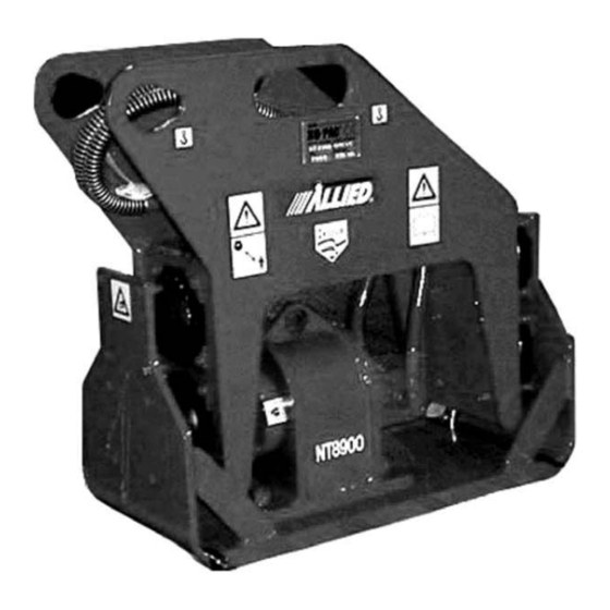
Page 7: Section 2.0 Overview
SECTION 2.0 OVERVIEW The Allied Ho-Pac is a boom-mounted, hydraulically-powered, vibrating-plate The DYNAMIC ASSEMBLY includes the compactor and driver. It is used for soil hydraulic motor, bearings, eccentric compaction and sheet/pile installation. mass, housing frame and base plate. The Ho-Pac is typically mounted on... -
Page 8: Section 3.0 Principles Of Operation
SECTION 3.0 PRINCIPLES OF OPERATION The Allied Ho-Pac is a high energy and the boom, plus the high impulse compaction tool utilizing three vibration forces produced by the Ho-Pac, compaction techniques: are ideal for compacting granular materials. The vibrations generate stress... -
Page 9: Section 4.0 Technical Information
SECTION 4.0 TECHNICAL INFORMATION 4.1 SPECIFICATIONS The following specifications apply to all configurations of the NT8900 Ho-Pac. Table 4-1 on the next page contains dimensions specific to each configuration. Impulse Force 6400 lbs (28,500N) Frequency 2000 bpm Sound Power Level 99 dBA (LWA)* Hydraulic Flow &... - Page 10 Table 4-1 NT8900 Ho-Pac Dimensions Flat Top Custom Weight 920** lbs (kg) (377) (417) (408) Height In.(mm) (916) (708) (814) Width In.(mm) (406) (406) (406) Depth In.(mm) (990) (965) (990) Mounting Pin Mounting Mounting Diameter Varies Bracket Bracket (in.(mm) Required Required Max Boom Width...
-
Page 11: Dimension Diagrams
4.2 DIMENSION DIAGRAMS 38.78 [985.01] 17.25 [438.15] 10.63 [269.88] 11.25 [285.75] 36.05 [915.80] 7.30 [185.42] 32.00 [812.80] 19.00 [482.60] 8.00 [203.20] 36.00 [914.40] 16.00 [406.40] Center of Gravity VMS V10 Dimension Diagram 7/21/03... - Page 12 21.75 [552.45] 17.00 [431.75] 37.97 [964.53] 32.05 [814.20] Center of Gravity { * } 32.00 [812.80] 8.00 [203.20] { * } 16.00 [406.40] 36.00 [914.40] Center of Gravity Custom Flat Top Dimension Diagram 7/21/03...
- Page 13 13.39 [340.00] 3.15 [80.01] 10.62 [269.87] 6.30 [160.02] 27.86 [707.66] { * } 32.00 [812.80] 8.00 [203.20] 16.00 [406.40] { * } 36.00 [914.40] Center of Gravity BCS Dimension Diagram 7/21/03...
-
Page 14: Decal Identification
The ALLIED LOGO decal is the Allied brand identifier and is a registered trademark of Allied Construction Products, LLC. The Model Number decal indicates the Ho-Pac model number. -
Page 15: Decal, Lifting And Lubrication Diagrams
4.4 DECAL, LIFTING AND LUBRICATION DIAGRAMS VMS, V10 Ho-Pac -Decal and Lubrication Drawing 7/21/03... - Page 16 Item Qty. Part No. Description Only 676980 ID Plate 676982 Lift Point 676985 Grease 8 hr. 676981 Stay Clear 676984 Read Instructions 676983 Hot Surface 676653 Allied Logo 102210 Decal-Model NT8900 818676 Pressure ID Tag (Located on Pressure Hose) 7/21/03...
-
Page 17: Section 5.0 Mounting Information
SECTION 5.0 MOUNTING INFORMATION 5.1 VMS Mounting The VMS mounting kit contains two collars, two plugs, and two pins as shown in the diagram below. The combination of the VMS design frame and a VMS mounting kit provides unequaled versatility and ease in attaching the units to carriers, and in transferring a Ho-Pac from one carrier to another.. -
Page 18: Bcs Mounting
Ho-Pac top plate as hardware varies by application and is shown below. Brackets are available for configured by Allied based on carrier each mounting type and can be custom specifications. The illustration shown designed when required. Each mounting below is a typical bracket;... -
Page 19: Swivel Mount
This is the carrier. especially good for compaction in trenches, or whenever the area of For more detailed swivel information operation is not in line with the contact Allied Construction Products or an Allied distributor. Swivel Mounting 7/21/03... -
Page 20: Section 6.0 General Construction Safety
SECTION 6.0 GENERAL CONSTRUCTION SAFETY 6.1 Owner’s Responsibilities Labor. For OSHA construction guidelines contact your local federal The equipment owner shall: government office or write: Provide this technical manual to the U.S. Government Printing Office Ho-Pac operators. Superintendent of Documents Train all operating personnel and P.O. -
Page 21: Personnel Precautions
technicians review these 6.4.2 Personnel Precautions CAUTIONS and WARNINGS prior to performing a procedure. CAUTIONS and Always wear safety glasses and WARNINGS are highlighted by the protective clothing when operating or symbol shown here and explained as handling the Ho-Pac. follows: All personnel in the immediate area must wear ear protection. - Page 22 SECTION 7.0 CARRIER APPLICATION The Allied NT8900 Ho-Pac is designed While the Ho-Pac is designed to for use and installation on medium to minimize the vibrations induced into the large rubber tire backhoe loaders and carrier, the operator must be isolated small excavators.
-
Page 23: Section 8.0 Installation & Removal
SECTION 8.0 INSTALLATION & REMOVAL 8.1 Installation 3. Follow hydraulic and mounting kit ~WARNING~ installation instructions. Always wear gloves and eye protection when connecting hydraulic connections, ~WARNING~ and installing mounting pins and Keep hands and fingers clear of hardware. mounting pin holes, carrier linkage and other pinch points while equipment is being positioned. -
Page 24: Removal
8.2 Removal 1. Position Ho-Pac safely on the ground. WARNING 2. Remove hydraulic connections. Always wear gloves and eye protection when disconnecting hydraulic con- 3. Be sure unit is stable prior to nections, and removing mounting pins removing mounting hardware. and hardware. -
Page 25: Section 9.0 Operation
SECTION 9.0 OPERATION The Ho-Pac is designed to operate with 3. Daily, lubricate bearings. See Section the carrier over a wide range of 11.5. temperatures. Refer to the carrier’s recommendations for operating tem- 4. Prior to compaction, the excavation perature range. shall be back-filled using other equip- ment. - Page 26 ~WARNING~ 10. It may be necessary to adjust the Never activate the Ho-Pac unless the idle speed of the carrier to maintain operator is seated in the operator’s proper Ho-Pac flow requirements. seat and in full control of the machine. Refer to carrier instructions.
-
Page 27: Section 10.0 Troubleshooting
Check hydraulic supply system. c. Motor worn or motor seals Correct as required. failed. Inspect and replace motor. b. Failed spring mount. Inspect and replace failed mount. For conditions other than these, contact the Allied Technical Service Depart- ment. 7/21/03... -
Page 28: Section 11.0 Service And Maintenance
Clean and properly dispose of any spilled Ho-Pac. oil as required by governing regulations. ~WARNING~ Contact the Allied Technical Service Follow all safety practices and wear Department with questions regarding appropriate protective equipment. maintenance, operation or replacement parts. -
Page 29: Conditional Maintenance
11.5 Lubrication 11.6 Bolts The Allied Ho-Pac is simply lubricated Because the Ho-Pac is a vibratory tool, it through standard lubrication fittings. is extremely important that threaded See lubrication diagram in Section 4.4. -
Page 30: Bearing Failure & Replacement
3. Slowly press the bearing into the housing. Apply contact pressure to the outer race only. ~CAUTION~ Use only Allied replacement parts. 4. Install one bearing and housing onto the eccentric shaft. 5. Align in main housing. 7/21/03... -
Page 31: Spring Mounts
Section 11.6. one mount at a time. 11.9 Hydraulic Motor 9. Install hydraulic hoses. There are no user-servicable parts in the hydraulic motor. Contact the Allied 10. After completely assembled, follow Technical Service Department for installation and daily lubrication further information. -
Page 32: Section 12.0 Lifting & Transport
SECTION 12.0 LIFTING & TRANSPORT 12.1 Lifting & Transporting Off Carrier 12.2 Lifting & Transporting On Carrier If the Ho-Pac is to be transported in- If the Ho-Pac is transported while dependently of the carrier; installed on the carrier: 1. Remove all loose debris from Ho- 1. -
Page 33: Section 13.0 Storage
SECTION 13.0 STORAGE Several simple precautions are necessary for storage of the Ho-Pac. 4. Support the Mounting Frame with blocks to minimize permanent sag 1. Protect hydraulic connections from. in spring mounts. Damage and debris. Plug hoses if hydraulic quick disconnects are not 5. - Page 34 This Page Intentionally Left Blank 7/21/03...
-
Page 35: Section 14.0 Parts Information
SECTION 14.0 PARTS INFORMATION NOTE The following illustrations and parts lists are typical models of the NT8900C Ho-Pac. Specific assemblies and mounting configurations may vary. 7/21/03... - Page 36 Dynamic Assembly and Suspension System 7/21/03...
- Page 37 Dynamic Assembly and Suspension System Part No. 101798 Item Qty. Part No. Description Only 708511 Hex Head Cap Screw 708512 Flat Washer 798197 Lubrication Nipple 708510 Cover Plate 708507 Roller Bearing 708508 Bearing Housing 708707 Eccentric 101814 Eccentric Housing 708787 Torque Nut 719730 Hex Head Cap Screw...
- Page 38 VMS, V10 Mounting Frame Ho-Pac 7/21/03...
- Page 39 VMS, V10 Mounting Frame Ho-Pac Part No. 101795 Item Qty. Part No. Description Only 670006 Q.D. Coupler Set (Includes Items 2 & 3) 670007 Q.D. Socket 670008 Q.D. Plug 670270 Check Valve, 5000 psi (S/N 8849 & Below) 667566 Hex Head Pipe Plug (S/N 8849 & Below) 708726 Adapter w/Port 659007...
- Page 40 Custom Flat Top Mounting Frame Ho-Pac 7/21/03...
- Page 41 Custom Flat Top Mounting Frame Ho-Pac Part No. 101833 Item Qty. Part No. Description Only 708818 20 GPM Flow Regulator Valve (S/N 8859 & Below) 103008 Motor & Flow Package (S/N 8850 & Above) Refer to Table 14.1 818329 Adapter 865384 Flat Washer (S/N 8849 &...
- Page 42 BCS Mounting Frame Ho-Pac 7/21/03...
- Page 43 BCS Mounting Frame Ho-Pac Part No. 102111 Item Qty. Part No. Description Only 656723 Adapter 865384 Flat Washer S/N 8849 &Below) 653339 Flat Washer (S/N 8850 & Above) 870368 Hex Head Cap Screw (S/N 8849 & Below) 814213 Hex Head Cap Screw (SN 8850 & Above) 678930 Hose Assembly (Return) (S/N 8849 &...
- Page 44 Table 14-1. Motor and Valve Pakcage 9 gpm, 14 gpm or 18 gpm Part No. Motor and Valve Package (one of the following*) 103006 Motor and Valve Package 12 gpm 101346 Hydraulic Motor 12 gpm 102650 Flow Regulator Valve 12 gpm 103007 Motor and Valve Package 18 gpm 102668...
- Page 45 This Page Intentionally Left Blank 7/21/03...
Need help?
Do you have a question about the Ho-Pac NT8900 Series and is the answer not in the manual?
Questions and answers