Table of Contents
Advertisement
Advertisement
Table of Contents
Troubleshooting

Related Manuals for PDi WaveStar


Summary of Contents for PDi WaveStar
- Page 1 ® WaveStar Color Monitor Setup and Operation Ctrl Nr: PM375103 Revision: 003...
- Page 2 For over 30 years, PDI has served the data center and alternative energy markets providing flexible solutions with the widest range of products in the industry.
-
Page 3: Table Of Contents
Contents________________________________________________________________________ Contents Safety .................... 6 Introduction ................7 WaveStar Color Monitor Summary ............7 Power On and Access ................. 7 Screen Summary and Navigation ............8 Entering Data ................... 8 Color Monitor Networking ........... 10 Supported Protocols ................ 10 Monitor Network Connections ............10 2.2.1... - Page 4 Tables Table 1 Pin-Out for Modbus Headers ....................11 Figures Figure 1 WaveStar Color Monitor Installed in a JCOMM ................ 7 Figure 2 HOME Screen and Navigation Buttons ..................8 Figure 3 Entering Alphanumeric Data ..................... 9 Figure 4 Color Monitor Network Connections ..................10 Figure 5 Color Monitor 4-wire Modbus Connections ................
- Page 5 Contents________________________________________________________________________ Figure 9 JCOMM Modbus Connections ....................14 Figure 10 Modbus Addressing ......................15 Figure 11 SETUP Screen ........................17 Figure 12 Calibrating the Touchscreen ....................17 Figure 13 Modbus RTU Setup ......................18 Figure 14 Modbus TCP/IP and SNMP Setup..................19 Figure 15 Model Information .........................
-
Page 6: Safety
Severe or fatal injury can result from electrical shock during contact with high voltage conductors, monitoring PCBs, or similar equipment. ® Disconnect power before drilling holes, attaching conduit, and attaching WaveStar Color Monitors to PDUs, RPPs, or other power distribution equipment. Use Lock Out/Tag Out procedures. -
Page 7: Introduction
The WaveStar ® Color Monitor is a 7-inch color touchscreen which displays power management information for up to twenty (20) Branch Circuit Monitoring System (BCMS) devices and other PDI devices in the Monitor’s downstream Modbus network. ® The Color Monitor is incorporated into PDI products, such as PDUs, RPPs, or JCOMM s, and can also function as a stand-alone power monitoring station. -
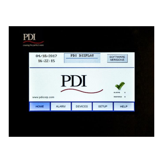
Page 8: Screen Summary And Navigation
WaveStar Color Monitor_____________________________________________________________ 1.3 Screen Summary and Navigation Banner, user-specified on SETUP screen Date/Time SOFTWARE VERSIONS button is only displayed on the HOME screen. Alarm summaries are given on each page. • The main navigation buttons are present on each screen. -
Page 9: Figure 3 Entering Alphanumeric Data
Introduction_____________________________________________________________________ Touch here to toggle between Symbol and Letters keyboards as you enter model information. Touch ENTER to complete the operation. Touch Cancel to terminate the operation. Figure 3 Entering Alphanumeric Data Ctrl Nr: PM375103 Revision: 003... -
Page 10: Color Monitor Networking
The Color Monitor’s backpanel has Modbus RTU and Ethernet ports (Figure 4). For Color Monitors embedded in PDI products (PDUs, RPPs, or JCOMMs), Modbus RTU backpanel connections are typically made in manufacturing and extended to a terminal block or external panel for convenient customer access. -
Page 11: Modbus Rtu Ports
Table 1 Pin-Out for Modbus Headers 2.2.2 Modbus RTU 2-Wire vs. 4-Wire Configuration PDI devices have two (2) jumpers near their Modbus ports for configuring 2-wire vs. 4-wire Modbus RTU (see Figure 4). The Monitor’s 2-wire configuration jumpers are W1 and W2 (upstream) and W3 and W4 (downstream). -
Page 12: Modbus Rtu Cables
The maximum length of Ethernet cable depends upon the customer’s choice of Ethernet cable. 2.5 Customer Modbus RTU Connections When a Color Monitor is embedded in a PDI product (PDU, RPP, or JCOMM), the customer does not typically wire Modbus RTU directly to the Monitor. Downstream Modbus RTU links are typically to internal devices and are wired at the factory. -
Page 13: Power Distribution Unit (Pdu)
Color Monitor Networking________________________________________________________ 2.5.1 Power Distribution Unit (PDU) On PDI PDUs, customers make Modbus RTU connections to the PDU’s Contractor Board. Basic and Enhanced Contractor Boards are shown (Figures 6, 7). Modbus RTU Modbus RTU Downstream Connection to Upstream internal PDU devices (usually wired at Connection factory). -
Page 14: Remote Power Panel (Rpp)
WaveStar Color Monitor_____________________________________________________________ 2.5.1 Remote Power Panel (RPP) On PDI RPPs the Color Monitor upstream Modbus connection is brought to a terminal block for convenient customer connection. Downstream connections are internal to the RPP and are wired at the factory. -
Page 15: Modbus Addressing
Color Monitor Networking________________________________________________________ 2.6 Modbus Addressing Monitor’s Upstream Modbus Segment Monitor’s Downstream Modbus Segment To upstream BCMS BCMS Modbus master (BMS, DCIM, etc.) PB1 PB2 PB3 PB4 30 = Monitor’s assigned upstream Downstream Modbus addresses must be address. assigned sequentially from 1. These addresses are visible from the upstream Modbus master: Downstream Modbus addresses are adjusted by... -
Page 16: Communicating With The Monitor: Commands And Replies
The following commands are supported and are typical for the product: • snmpget • snmpgetnext • snmpset See the MIB file for specifics. The MIB can be downloaded from the PDI website. Reference the Bibliography in this manual. Ctrl Nr: PM375103 Revision: 003... -
Page 17: Setup: Monitor And Network
A password is required to access and change setup parameters. Enter the password (default is “PDI”). The user can navigate through any of the screens and come back to SETUP without having to re-enter the password for 10 minutes. Touch PASSWORD to change to a new password. -
Page 18: Network Setup
WaveStar Color Monitor_____________________________________________________________ 3.2 Network Setup Note: Improper configuration of a WaveStar Color Monitor may conflict with other monitors or devices on the network. 3.2.1 Downstream Modbus Device Chain Setup To set Modbus device chain parameters, touch DEVICES/MODBUS (Figure 13): •... -
Page 19: Tcp/Ip And Modbus Tcp/Ip Setup
Color Monitor Networking________________________________________________________ • Upstream Modbus settings for Baud rate and Parity must match those for the upstream Modbus master. 3.2.3 TCP/IP and Modbus TCP/IP Setup For TCP/IP, the customer must provide an Ethernet cable connected to the Ethernet port (RJ45 header J11) on the Monitor. -
Page 20: Loading Ini Parameters From An Sd Card
WaveStar Color Monitor_____________________________________________________________ • Touch SEND TEST TRAP to verify operation. • Get Community security string for Get operations. • Set Community security string for Set operations. Touch RESTART WITH NEW SETTINGS if any parameter is changed on this screen. The processor will reboot and search the network for connections. - Page 21 Color Monitor Networking________________________________________________________ • Display Version Number is given by the Monitor’s onboard software. • Device Version Numbers are entered in device setup: Go to DEVICES screen, select device, select VERSION field, and enter data. Ctrl Nr: PM375103 Revision: 003...
-
Page 22: Device Chain: Settings
WaveStar Color Monitor_____________________________________________________________ 4 Device Chain: Settings A “device” is a points list (or Modbus register map) representing a physical monitored entity, such as a panelboard. Each points list instance has a single Modbus address. A single PCB can have multiple devices with their own Modbus addresses. A BCMS Data Acquisition Board, for example, can have two panelboard devices plus a small two-subfeed device, or up to three Modbus addresses. -
Page 23: Device Settings
Each device has a SETTINGS screen for changing device name, software version, and device configuration. These settings provide information to the Monitor in addition to each device’s own internal setup. Device settings will usually be entered by PDI manufacturing or service representatives, but can be entered by customer administrators. 4.2.1 PDU Device Settings PDU devices (Figure 17) have only two settings: device NAME and VERSION. -
Page 24: Enhanced Subfeeds Settings
WaveStar Color Monitor_____________________________________________________________ 4.2.2 Enhanced Subfeeds Settings BCMS Enhanced Subfeeds (ESF) devices are for large PDU subfeeds to other PDUs and RPPs. A single ESF Points List can monitor 1-14 subfeeds (Figure 18): • If CTs on installed on ABC-phases only, 14 subfeeds can be monitored. -
Page 25: Bcms Cb Subfeeds Settings
Device Chain: Settings ___________________________________________________________ Select (touch) BCMS KWH device name in DEVICES list. Device name turns blue when selected. NAME: Enter a unique device name (up to 16 characters); device name is propagated to header and device list. START: Number for first panelboard circuit, touch to increment +42 to next panelboard. -
Page 26: Bcms Iec Settings
WaveStar Color Monitor_____________________________________________________________ A BCMS Data Acquisition Board—the physical BCMS PCB— can have three BCMS devices with their own points lists: • Panelboard 1 points list, BCMS (Normal), BCMS KWH, or BCMS IEC • Panelboard 2 points list, using the type of points list as for Panelboard 1 •... -
Page 27: Device Chain: Readings
Device Chain: Readings ___________________________________________________________ 5 Device Chain: Readings Each device in the Monitor’s device chain has a READINGS screen chain, providing power monitoring information. • Select (touch) DEVICES to see the device list and then READINGS. • Use PREVIOUS/NEXT to step through the screen chain. 5.1 PDU Device Readings READINGS from the PDU are power measurements at input to and output from the PDU transformer (Figure 22). -
Page 28: Enhanced Subfeeds (Esf) Readings
WaveStar Color Monitor_____________________________________________________________ 5.2 Enhanced Subfeeds (ESF) Readings Readings from an Enhanced Subfeeds (ESF) device are typically power measurements and alarms for high amperage PDU circuits that are subfeeds to other PDUs or RPPs (Figures 23-24). Enhanced Subfeeds devices can monitor •... - Page 29 Device Chain: Readings ___________________________________________________________ NO: Subfeed circuit by number and phase Instantaneous measurements by phase: % LOAD: %Load is a percent of the Full Load amperage for this breaker; “Full Load” is a user-specified percent of breaker size, given in Modbus register 494 (“Full Load Percentage”) in the ESF Points List.
-
Page 30: Bcms (Normal) Panelboard Readings
WaveStar Color Monitor_____________________________________________________________ 5.3 BCMS (Normal) Panelboard Readings Select BCMS device name in list (BCMS in this list). Device name turns blue when selected and device name displays in header. Touch READINGS to see BCMS power monitoring data. Measurements and Alarms, individual... -
Page 31: Bcms Kwh Readings
Device Chain: Readings ___________________________________________________________ BCMS Normal points list allows customization of thresholds and alarm level for each individual circuit, which is done in BCMS setup, not in the Color Monitor. KWH Power measurements are available only for panelboard totals. See Figure 25, “Readings: BCMS Normal”. 5.4 BCMS KWH Readings Compared to BCMS Normal, BCMS KWH panelboard devices have one additional screen showing power measurements (KWH, etc.) for individual circuits. - Page 32 WaveStar Color Monitor_____________________________________________________________ Panelboard instantaneous readings: Voltage AB, BC, etc., to panelboard with THD (Total Harmonic Distortion %) by phase: Line 1 = voltage source 1 Line 2 = voltage source 2, if present Panelboard power measurements by phases ABC and total:...
-
Page 33: Bcms Cb (Subfeeds) Readings
Device Chain: Readings ___________________________________________________________ 5.5 BCMS CB (Subfeeds) Readings The short BCMS CB (Subfeeds) points list is associated with panelboard BCMS Normal or KWH points lists and provides current readings for two subfeeds (Figure 28). It is typically used with an RPP, which can have subfeeds to other power distribution equipment in addition to its panelboards. - Page 34 WaveStar Color Monitor_____________________________________________________________ Touch BCMS IEC device name in the device name list. Device name turns blue when selected and device name displays in header. (Device name can be changed in SETTINGS.) Touch READINGS to see BCMS IEC panelboard power monitoring data in three screens.
-
Page 35: Alarms And Troubleshooting
Alarms and Troubleshooting_________________________________________________________ 6 Alarms and Troubleshooting The Color Monitor displays alarms and warnings for all devices in the Monitor’s device chain. The Monitor reads the alarms and warnings from the points list (Modbus register map) of each device. 6.1 Summary Alarm Indicators The Color Monitor indicates that there are extant alarms with three general indicators: •... - Page 36 WaveStar Color Monitor_____________________________________________________________ 5. Scroll within the circuit list on the first device screen to find circuit or other component in warning/alarm. An alarm may apply to a circuit or to the entire device, such as “Under Current PB.” Touching CLEAR ALL clears...
-
Page 37: Alarms By Device Type
Alarms and Troubleshooting_________________________________________________________ 6.3 Alarms by Device Type Each device has its own alarm set based on its points list. Warnings and alarms that can be viewed on the Monitor are listed below. The Monitor does not display setpoints from the points lists, such as alarm thresholds. - Page 38 WaveStar Color Monitor_____________________________________________________________ PDU Transformer Input Alarm Alarm Description NOTE: If the PDU is configured for dual inputs, “Input 1” or “Input 2” will prefix the alarm instead of “Input.” Input Voltage AB High Input voltage AB measures above threshold level in points list.
-
Page 39: Enhanced Subfeeds
Alarms and Troubleshooting_________________________________________________________ Alarm Alarm Description Output Current A High Output current phase A measures above threshold level in points list. Output Current A Low Output current phase A measures below threshold level in points list. Output Current B High Output current phase B measures above threshold level in points list. -
Page 40: Bcms Panelboard-Typical Alarms
WaveStar Color Monitor_____________________________________________________________ Alarm Alarm Description Under Voltage Under voltage measured to ESF board as specified in points list. 6.3.4 BCMS Panelboard—Typical Alarms Circuit Alarms Alarm Alarm Description Note: The Color Monitor can number panelboard circuits sequentially for up to 336 circuits (8 x 42- circuit panelboards) as specified in device setup. - Page 41 Alarms and Troubleshooting_________________________________________________________ SYMPTOM PROBABLE CAUSE REMEDY Monitor has Open connection or lose wire Check wiring. Refer to “Modbus” AND communication errors. on the Modbus chain. Display “Setup” previously in this manual. Refer may not be properly setup. to initial setup to setup downstream units.
-
Page 42: Web
Each web page has three buttons: • Click Home to return to Color Monitor Home page. • Click PDI to display the PDI web page. • Click Devices to display a list of all devices in the Color Monitor’s downstream chain. - Page 43 Web Pages______________________________________________________________________ The first device in the Devices list (Figure 34) is the Color Monitor itself, whose web page only shows the number of devices in the Monitor’s device chain, firmware level, and a user-defined model ID (Figure 35). Figure 35 Web Pages: Display Device The remaining devices have monitoring data.
- Page 44 WaveStar Color Monitor_____________________________________________________________ Device type: M4GACK = PDU Acquisition Board No alarms for this device. Modbus address (downstream from Monitor) = 2 Device name = PDU PDU board data is shown in series of tabbed screens. Click tab to view screen.
- Page 45 Web Pages______________________________________________________________________ Device type: BCMS ESF (subfeeds group) Modbus address (downstream from Monitor) = 3 Device name = BCMS ESF Subfeed data is shown in series of tabbed This device has screens. Click tab to view screen. alarms and warnings, see bar chart.
-
Page 46: Glossary
WaveStar Color Monitor_____________________________________________________________ Glossary BCMS Branch Circuit Monitoring System. BCMS device Power distribution elements monitored by a single points list (or Modbus register map) and addressed by a single Modbus address. Example: a panelboard is a BCMS device because it is monitored with one points list and has one Modbus address. -
Page 47: Bibliography
“72 BCMSII plus points list Europe KWH”. For PDU points lists, download the WaveStar® PDU Customer CD, a zip file. Unzip the file and open the directory \Points List for WaveStar PDU & BCMS Version to find these points lists and use the latest revision given: •... -
Page 48: Appendix: Color Monitor Backpanel
• Battery: Lithium ion, Panasonic-BSG (CR2477), 3V, 1 AH (PDI Part Number 15174) Caution: The battery used in this device may present a risk of fire or chemical burn hazard if mistreated. Do not recharge, disassemble, heat above 100°C (212°F) or incinerate. Replace... - Page 49 Appendix: Color Monitor Backpanel__________________________________________________ battery with Panasonic-BSG (CR2477), 3V, 1 AH (PDI Part Number 15174) only. Use of another battery may present a risk of fire or explosion. Dispose of used battery promptly. Keep away from children. Do not disassemble and do not depose of in fire.
Need help?
Do you have a question about the WaveStar and is the answer not in the manual?
Questions and answers