Table of Contents
Advertisement
Quick Links
Advertisement
Table of Contents

Subscribe to Our Youtube Channel
Summary of Contents for Tyco American Dynamics iSCSI RAID Storage
- Page 2 User Manual iSCSI RAID Storage Fibre RAID Storage Expansion RAID Storage 3U Rack Mount Version 2 Version 1.1 Part Number: 8200-2723-07 A0...
- Page 3 Under copyright laws, the contents of this manual may not be copied, photocopied, reproduced, translated or reduced to any electronic medium or machine-readable form, in whole or in part, without prior written consent of Tyco International Ltd. Copyright © 2010 Tyco International Ltd. and its Respective Companies. All Rights Reserved.
-
Page 4: Safety Information
Safety Information Technician Notes Warning Only authorized technicians should attempt to repair this equipment. All trouble shooting and repair procedures allow only module replacement. Because of the complexity of the individual boards and sub- assemblies, no one should attempt to make repairs at the component level or make modifications to any printed wiring board. -
Page 5: Rack Warnings
Rack Warnings If you plan to rack mount the iSCSI RAID Storage, Fibre RAID Storage or the Expansion RAID Storage System, please follow the rack manufacturer’s safety instructions. Install the enclosure only in a rack that has been properly secured in an area with suitable environmental conditions. Caution Have someone assist you during physical installation. -
Page 6: Table Of Contents
Table of Contents Safety Information ......................iii Technician Notes ......................iii Electrostatic Discharge ....................iii Rack Warnings ......................iv System Warnings ......................iv Overview ........................1 1.1 Features ....................... 1 1.1.1 Specifications ..................2 ... - Page 7 4.1.3 Login setting ..................33 4.1.4 Mail setting ..................34 4.1.5 Notification setting ................35 4.2 iSCSI configuration (Only on iSCSI RAID Storage) ........... 36 4.2.1 Entity property .................. 36 4.2.2 NIC ....................
-
Page 8: Overview
1.0 Overview 1.1 Features The second generation American Dynamics® iSCSI and Fibre RAID Storage solutions are designed for high-performance recording devices. They are secure and highly scalable storage solutions that provide SAN storage for virtually any network and application. The new Rack Mount models are available in a variety of configurations and capacities. -
Page 9: Specifications
1.1.1 Specifications Storage Type iSCSI RAID Storage Fibre RAID Storage Expansion Storage Hardware RAID Single Controller Single Controller Single Controller Controller Intel XScale IOP81342 Intel XScale IOP81341 LSI SAS Expander Processors 1GB DDR667 1GB DDR667 Memory 0,1,0+1,3,5,6,10,30,50,60, JBOD and N-way Mirror RAID Levels Supported Drives per... -
Page 10: Raid Concepts
RAID concepts RAID is the abbreviation of Redundant Array of Independent Disks. The basic idea of RAID is to combine multiple drives together to form one large logical drive. This RAID drive obtains performance, capacity and reliability than a single drive. -
Page 11: Storage Concepts
transaction. LUN (Logical Unit Number) is a unique identifier, in which users can access through SCSI commands. LUN 1 LUN 2 LUN 3 VD 1 VD 2 VD 3 Cache Volume PD 1 PD 2 PD 3 Storage Concepts 1.3.1 iSCSI iSCSI (Internet SCSI) is a protocol which encapsulates SCSI (Small Computer System Interface) commands and data in TCP/IP packets for linking storage devices with servers over common IP infrastructures. - Page 12 requests all SCSI operations like read or write. An initiator is usually located on the host side (either an iSCSI HBA or iSCSI SW initiator). The target is the storage device itself or an appliance which controls and serves volumes or virtual volumes. The target is the device which performs SCSI command or bridge to an attached storage device.
-
Page 13: Fibre Channel
1.3.2 Fibre Channel Fibre channel started use primarily in the supercomputer field, but has become the standard connection type for storage area networks (SAN) in enterprise storage. Host 2 Host 1 (initiator) (initiator) FC HBA FC HBA FC device 1 (target) FC device 2 (target) The target is the storage device itself or an appliance which controls and serves volumes or virtual volumes. -
Page 14: Hardware Components
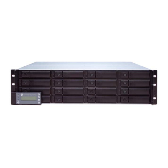
2.0 Hardware Components 2.1 iSCSI RAID Storage 3U Rack Mount Version 2 What’s in the Box: • 1 x iSCSI Raid Storage-3U Rack • 16 x Hard Drive Modules • 1 x Serial Console Cable • 1 x SAS Cable •... -
Page 15: Enclosure
2.1.1 Enclosure Front view The drives can be installed into any slot in the enclosure. Slot numbering will be reflected in web UI. Note It’s better to install at least one drive in slot 1 ~ 4. System event logs are saved in these drives. -
Page 16: Fibre Raid Storage 3U Rack Mount Version 2
2.2 Fibre RAID Storage 3U Rack Mount Version 2 What’s in the Box: • 1 x Fibre Raid Storage-3U Rack • 16 x Hard Drive Modules • 1 x Serial Console Cable • 1 x SAS Cable • 2 x Power Cables •... -
Page 17: Enclosure
2.2.1 Enclosure Front view The drives can be installed into any slot in the enclosure. Slot numbering will be reflected in web UI. Note It’s better to install at least one drive in slot 1 ~ 4. System event logs are saved in these drives. -
Page 18: Expansion Raid Storage 3U Rack Mount Version 2
Fibre Channel Connector LEDs Link LED FC 2 Link LED FC 1 Access/Fail LED FC 2 Access/Fail LED FC 1 Yellow/Blue 1Gb link is established and maintained Link LED Yellow 2Gb link is established and maintained Blue 4Gb link is established and maintained FC link is established and packets are Yellow being transmitted along with any receive... -
Page 19: Enclosure
2.3.1 Enclosure Front View The drives can be installed into any slot in the enclosure. Slot numbering will be reflected in web UI. Rear View Power Power Power Switch Power Supply Power Supply Unit (PSU2) Unit (PSU1) Fan Module Fan Module (FAN2) (FAN1) SAS OUT... -
Page 20: Lcd Control Panel
2.4 LCD Control panel There are five buttons to control the LCD Control Module, including: (up), (down), Enter, ESC (Escape) and Mute. LCD Display Power LED Up Button Access LED Down Button Status LED Enter Button Mute Button ESC Button (Escape) LCD LED Description Blue Power ON... -
Page 21: Hdd Tray
2.5 HDD tray Remove a drive tray. Then install a HDD. Tray Release HDD Tray Handle Button HDD Fault LED HDD Activity LED Hard Drive Tray Description Hard Drive Failure HDD Fault LED Hard Drive is Good Blue Active Hard Drive HDD Activity LED Violet Blinking Hard Drive Access... -
Page 22: Connections
2.6 Connections 2.6.1 iSCSI Please refer to the following topology and have all the connections ready. iSCSI RAID Storage Expansion RAID Storage To next Expansion RAID Storage Before starting, prepare the following items. • A host with a Gigabit Ethernet NIC or iSCSI HBA. •... - Page 23 • Prepare management port and iSCSI data ports network information. When using static IP, please prepare static IP addresses, subnet mask, and default gateway. • Gigabit LAN switches (recommended). Or Gigabit LAN switches with VLAN / LCAP / Trunking (optional). •...
-
Page 24: Fibre Channel
2.6.2 Fibre Channel Please refer to the following topology and have all the connections ready. Fibre RAID Storage Expansion RAID Storage To next Expansion RAID Storage User Manual 1.1... -
Page 25: Expansion Raid Storage
Before starting, prepare the following items. • A server with a FC HBA. • FC cables. • CAT 5e, or CAT 6 network cables for management port. • Prepare storage system configuration plan. • Prepare management port network information. When using static IP, please prepare static IP addresses, subnet mask, and default gateway. - Page 26 To connect an Expansion RAID Storage System to a primary unit (iSCSI or Fibre RAID Storage): • Connect the primary unit (iSCSI RAID Storage or Fibre RAID Storage) “JBOD” connector to the Expansion #1’s I/P1 Connector. The O/P connector on Expansion #1 will connect to the next Expansion RAID Storage (if applicable).
- Page 27 After all of the cables are connected, power on the Expansion units first and then power on the primary unit. Expansion RAID Storage Systems are configured through the Management Interface of the iSCSI or Fibre RAID Storage System. When an Expansion unit has been detected, it will display as a link on the top of the page.
-
Page 28: Quick Setup
3.0 Quick Setup 3.1 Management interfaces There are three management methods to manage the iSCSI RAID Storage and the Fibre RAID Storage Systems: 3.1.1 Serial console Use console cable (NULL modem cable) to connect from console port of the iSCSI/Fibre RAID Storage to the RS-232 port of the management PC. The console settings are on the following: Baud rate: 115200... -
Page 29: Cd Control Module (Lcm)
3.1.3 CD Control Module (LCM) After booting up the system, the following screen shows management port IP and model name: 10.10.10.20 AD iSCSI RAID Rack← Press Enter button, the LCM functions System Info., Alarm Mute, Reset/Shutdown, Quick Install, Volume Wizard, View IP Setting, Change IP Config and Reset to Default will rotate by pressing (up) and (down). - Page 30 LCM operation description: Display system information. System Info. Mute alarm when error occurs. Alarm Mute Reset or shutdown controller. Reset/ Shutdown Quick steps to create a volume. Please refer to next Quick Install chapter for detailed operation steps in web UI. Smart steps to create a volume.
- Page 31 iSCSI RAID Storage and Fibre RAID Storage LCM menu hierarchy: [Firmware Version [System Info.] x.x.x] [RAM Size xxx MB] [Alarm Mute] [ Yes No ] [ Yes [Reset] No ] [Reset/Shutdown] [ Yes [Shutdown] No ] RAID 0 RAID 1 RAID 3 [Quick Install] RAID 5...
- Page 32 Caution Prior to any Power OFF, it is highly recommended to “Shutdown” to flush the data from the cache to the physical disks. Expansion RAID Storage LCM menu hierarchy: [Alarm From] [Alarm From] xxxxxx [Alarm Mute] [ Yes No ] [ PSU1] [Power Supply] [O/X]...
-
Page 33: Web Ui
3.1.4 Web UI A web based graphical user interface (GUI) is available for management. Make sure the Management Port Ethernet cable is connected. Using any web browser, enter in the IP address of the iSCSI or Fibre RAID Storage. (By default, the Storage System is configured to use DHCP to obtain a valid IP Address.) The IP address is on the LCD Display on the front of the iSCSI/Fibre RAID Storage. - Page 34 After login, select the functions from the list on the left side of window for any configuration modifications. There are six indicators at the top-right corner for backplane solutions. Indicator description: Indicator Color Indication Green RAID RAID Failed RAID Normal Green Temperature Abnormal...
-
Page 35: How To Use The System Quickly
3.2 How to use the system quickly The following methods will describe the quick guide to use this subsystem. 3.2.1 Quick installation It is easy to use “Quick install” to create a volume. It uses whole physical disks to create a RG; the system will calculate maximum spaces on RAID levels 0 / 1 / 3 / 5 / 6 / 0+1. -
Page 36: Volume Creation Wizard
3.2.2 Volume creation wizard “Volume create wizard” has a smarter policy and can be used when the system is filled with some Hard Disk Drives. Using all available HDDs, “Volume create wizard” lists all the possibilities and sizes for different RAID levels. - Page 37 Step 3: Decide VD size. Any value less than or equal to the default number can be entered. Then click “Next”. Step 4: Confirm page. Click “Confirm” if all setups are correct. Then a VD will be created. Step 5: The Volume is created. The system can be used.
-
Page 38: Configuration
4.0 Configuration 4.1 System configuration In System configuration the settings for the iSCSI RAID/Fibre RAID Storage are configured. 4.1.1 System setting In System Setting the system name and date can be configured. The default System name is composed of the model of this system. User Manual 1.1... -
Page 39: Ip Address
Before using the system, check Change date and time to set up the current date, time, and time zone or synchronize time from NTP (Network Time Protocol) server. 4.1.2 IP address In IP address, the IP address can be changed. This is the IP address for the management port which is used for remote administration usage. -
Page 40: Login Setting
4.1.3 Login setting In Login setting changes to the administrator and user account can be configured. Auto logout: The system will log out automatically when the user is inactive for the specified period of time. The options are: • Disabled •... -
Page 41: Mail Setting
Check the checkbox for Change admin password or Change user password to change admin or user password. The maximum length of password is 12 characters. 4.1.4 Mail setting Up to three email addresses can be configured for receiving event notification. Some mail servers check the Mail-from address and authentication is required. -
Page 42: Notification Setting
4.1.5 Notification setting In the Notification setting screen other methods of event notification can be configured. The following can be configured: • SNMP trap for alerting via SNMP • Pop-up message via Windows messenger (not MSN) • Alert via syslog protocol •... -
Page 43: Iscsi Configuration (Only On Iscsi Raid Storage)
Selecting Always disable buzzer the system will not alarm with an audible alert when an error occurs. 4.2 iSCSI configuration (Only on iSCSI RAID Storage) iSCSI configuration is designed for setting up the iSCSI related properties. These settings are only available on the iSCSI RAID Storage systems. 4.2.1 Entity property In Entity property the entity name of the system in this location and the setup for iSNS (Internet Storage Name Service). - Page 44 IP settings The IP address can be changed by selecting the gray button by the LAN port, a menu will appear select IP settings for iSCSI ports from the menu. The IP address can be obtained from DHCP(get IP address from DHCP server) or a static IP.
- Page 45 Multi-homed / Trunking / LACP: The following is the description of multi-homed / trunking / LACP functions. Multi-homed: Default mode. Each iSCSI data port is unique and there is no link aggregation or trunking. This function is also used for Multipath functions. Select this mode will remove any Trunk/LACP setting.
-
Page 46: Node
4.2.3 Node The iSCSI RAID Storage supports multi-nodes. There is no default node name, so it must be created prior to use. When using Quick install, a node name will automatically be created. CHAP: CHAP is the abbreviation of Challenge Handshake Authorization Protocol. CHAP is a strong authentication method used in point-to-point for user login. -
Page 47: Session
Step 4: First a CHAP account needs to be created on the iSCSI configuration / CHAP account page. Step 5: On the iSCSI configuration / Node page, check the gray button in the Auth column and select User. Step 6: Select CHAP user(s) which will be used for the Node. Multiple users can be selected. -
Page 48: Chap Account
4.2.5 CHAP account The CHAP account page manages a CHAP account for authentication. Multiple CHAP accounts can be created. To setup a CHAP account: Step 1: Select the Create button. Step 2: Enter User, Secret, and Confirm the secret again. The Node can be selected here or later. -
Page 49: Physical Disk
4.3.1 Physical disk The status of all of the hard drives can be viewed on the Physical disk page. - Page 50 PD column description: The position of a hard drive. The button next to the Slot number of slot shows the functions which can be executed. Capacity of hard drive. The unit can be displayed in Size (GB) GB or MB. (MB) RAID group name.
-
Page 51: Raid Group
Selecting the gray button next to the number of slot will display a menu of additional functions which can be executed. Active function can be selected. Inactive functions show up in gray color and cannot be selected. PD operation description: Makes the selected hard drive free for use. - Page 52 RG column description: RAID group number. The button next to the No. includes the functions which can be executed. RAID group name. Name Total capacity of this RAID group. The unit can be Total (GB) (MB) displayed in GB or MB. Free capacity of this RAID group.
- Page 53 RG operations Create a RAID group. Create Change the RAID level of a RAID group. Migrate Activate a RAID group after disk roaming; it can be Activate executed when RG status is offline. This is for online disk roaming. Deactivate a RAID group before disk roaming; it can be Deactivate executed when RG status is online.
- Page 54 To create a RAID group Select the create button. The Volume Configuration / RAID group / Create page appears. Enter the Name, select the RAID level and select PD to select the physical disks that will make up the RAID group. Select the settings for the Write cache, Standby, Readahead and Command queuing.
-
Page 55: Virtual Disk
4.3.3 Virtual disk The Virtual disk page displays the status of each Virtual Disk. - Page 56 VD column description: Virtual Disk number. The button next to the number includes the functions which can be executed. Virtual disk name. Name Total capacity of the virtual disk. The unit can be Size (GB) (MB) displayed in GB or MB. The write cache policy of the virtual disk: Right WT –...
- Page 57 Virtual Disk Operations Extend the capacity of a virtual disk capacity. Extend Scrub a Virtual disk for parity regeneration. It supports Scrub RAID 3 / 5 / 6 / 30 / 50 / 60. Delete a virtual disk. Delete Change the VD name, write cache, priority, background Set property task priority and read ahead.
-
Page 58: Snapshot
To create a Virtual Disk Select the create button. The Volume Configuration / Virtual disk / Create page appears. Enter the Name, select the RAID group from the pull down list of RG names and enter the capacity. Select the settings for Stripe height, Block size, read and write cache, Priority, Background priority and readahead. - Page 59 Snapshot column description: The number of this snapshot VD. The button next to the snapshot VD No. includes the functions which can be executed. Snapshot VD name. Name The amount of snapshot space that has been used. The Used (GB) unit can be displayed in GB or MB.
- Page 60 To create a snapshot Step 1: Create the snapshot space. On the / Volume configuration / Virtual disk page, select the gray button next to the VD number. A menu will appear. Select Set snapshot space. Step 2: Set the snapshot space and then select Confirm. Step 3: The snapshot space is created.
-
Page 61: Logical Unit
Export the snapshot VD Select the button next to the Snapshot VD number. Select Export. Enter a capacity for snapshot VD. If the size is zero, the exported snapshot VD will be read only. Otherwise, the exported snapshot VD will be read/write. 4.3.5 Logical unit The Logical unit page displays the status of attached logical unit number(s) of each Virtual Disk. - Page 62 LUN operation description: Attach a logical unit number to a virtual disk. Attach Detach a logical unit number from a virtual disk. Detach The matching rules of access control are followed from the LUNs’ created time; the earlier created LUN is prior to the matching rules. Wildcard “*”...
-
Page 63: Enclosure Management
4.4 Enclosure Management Enclosure management manages enclosure information including “SES configuration”, “Hardware monitor”, “S.M.A.R.T.” and “UPS”. For the enclosure management, there are many sensors for different purposes, such as temperature sensors, voltage sensors, hard disk status, fan sensors, power sensors, and LED status. Due to the different hardware characteristics among these sensors, they have different polling intervals. -
Page 64: Hardware Monitor
4.4.2 Hardware monitor On the Hardware monitor page the information of current voltages and temperatures can be viewed. If Auto shutdown is checked, the system will shutdown automatically when voltage or temperature is out of the normal range. For better data protection, check Auto Shutdown. -
Page 65: Hard Drive S.m.a.r.t. Support
4.4.3 Hard drive S.M.A.R.T. support S.M.A.R.T. (Self-Monitoring Analysis and Reporting Technology) is a diagnostic tool for hard drives to deliver a warning of drive failures in advance. S.M.A.R.T. provides users the opportunity to take preventative action before a possible drive failure. S.M.A.R.T. -
Page 66: System Maintenance
UPS description: Select UPS Type. Choose Smart-UPS for APC, UPS Type None for other vendors or no UPS. When the battery level is below the setting level, Shutdown Battery system will shutdown. Setting level to “0” will Level (%) disable UPS. If a power failure occurs and system power cannot Shutdown Delay recover, the system will shutdown. -
Page 67: System Information
4.5.1 System information System information displays system information including version and contact information to get technical assistance for this product. -
Page 68: Upgrade
4.5.2 Upgrade Firmware can be upgraded on the Upgrade page. Have the new firmware file “xxxx.bin” available to the local client system. Select the Browse button to select the new firmware files. Select the Confirm, it will pop up a message “Upgrade system now? If you want to downgrade to the previous FW later (not recommend), please export your system configuration in advance”. -
Page 69: Import And Export
When resetting back to the factory default setting values, the default values are: Default Login: admin Default Password: admin Default IP address: DHCP 4.5.4 Import and export Import and export allows user to save system configuration values (export) and apply a saved configuration (import). For the volume configuration setting, the values are available for export but they are not available for import. -
Page 70: Event Log
4.5.3 Event log Event messages can be viewed in the Event log pages. The level of the events to display can be selected by selecting the checkbox of INFO, WARNING, and ERROR. Selecting the Download button saves the whole event log as a text file with file name “log-ModelName-SerialNumber-Date- Time.txt”. -
Page 71: Reboot And Shutdown
4.5.4 Reboot and shutdown The iSCSI RAID Storage and the Fibre RAID Storage can be reboot and shutdown from the Reboot and shutdown page. The shutdown command will flush the data from the cache to the physical disks before the unit is powered off. -
Page 72: Advanced Operations
5.0 Advanced Operations 5.1 Volume rebuild If one physical disk of the RG which is set as protected RAID level (e.g.: RAID 3, RAID 5, or RAID 6) is FAILED or has been unplugged / removed, then the status of RG is changed to degraded mode, the system will search/detect spare disk to rebuild the degraded RG to a complete one. - Page 73 Rebuild operation description: Disk striping. No protection for data. RG fails if any hard RAID 0 drive fails or is removed. Disk mirroring over 2 disks. RAID 1 allows one hard drive RAID 1 to fail or be removed. One new hard drive needs to be inserted into the system and the rebuild will complete.
-
Page 74: Rg Migration
5.2 RG migration To complete a migration, the total size of RG must be larger or equal to the original RG. It does not allow expanding the same RAID level with the same hard disks of original RG. During a RG migration the following operations are not allowed: •... -
Page 75: Disk Roaming
Step 4: Extension starts. If VD needs initialization, it will display an Initiating in Status and complete percentage of initialization in R%. Note The size of VD extension must be larger than original. Caution VD Extension cannot be executed during rebuilding or migration. 5.4 Disk roaming Physical disks can be re-sequenced in the same system or move all physical disks in the same RAID group from system-1 to system-2. - Page 76 Disk roaming has some constraints: • Check the firmware version of two systems first. It is better that both systems have the same firmware version or the firmware for system-2 is newer. • All physical disks of the RG should be moved from system-1 to system-2 together.
-
Page 78: Troubleshooting
6.0 Troubleshooting 6.1 System buzzer The system buzzer features are listed below: • The system buzzer alarms for one second when system boots up successfully. • The system buzzer alarms continuously when an error occurs. The alarm will stop after the error is resolved or muted. •... - Page 79 Thermal critical System Overheated <item>!!! ERROR Thermal critical System Overheated <item>!!! The system will auto- ERROR shutdown shutdown immediately. Thermal ignore Unable to update thermal value on <item>. WARNING value Voltage warning System voltage <item> is outside normal range. WARNING Voltage critical System voltages <item>...
- Page 80 VD migration VD <name> completes migration. INFO finished VD migration failed Failed to complete migration of VD <name>. ERROR VD scrubbing VD <name> starts scrubbing. INFO started VD scrubbing VD <name> completes scrubbing. INFO finished RG migration RG <name> starts migration. INFO started RG migration...
- Page 81 Snapshot events Level Type Description Snapshot deleted The snapshot VD <name> has been deleted. INFO Snapshot auto The oldest snapshot VD <name> has been deleted to INFO deleted obtain extra snapshot space. Snapshot taken A snapshot on VD <name> has been taken. INFO Snapshot space Set the snapshot space of VD <name>...
- Page 82 configured a global spare disk. PD read error Read error occurred at LBA <address>-<address> of WARNING occurred JBOD <number> PD <slot>. PD write error Write error occurred at LBA <address>-<address> of WARNING occurred JBOD <number> PD <slot>. PD freed JBOD <number> PD <slot> has been removed from INFO RG <name>.
-
Page 84: Glossary And Acronyms
Glossary and Acronyms Battery Backup Module Challenge Handshake Authentication Protocol. An optional CHAP security mechanism to control access to an iSCSI storage system over the iSCSI data ports. DeGraded mode. Not all of the array’s member disks are functioning, but the array is able to respond to application read and write requests to its virtual disks. - Page 85 SCSI Enclosure Services. Virtual Disk. Each RD could be divided into several VDs. The VDs from one RG have the same RAID level, but may have different volume capacity. Write-Back cache-write policy. A caching technique in which the completion of a write request is signaled as soon as the data is in cache and actual writing to non-volatile media occurs at a later time.
- Page 86 User Manual 1.1...
- Page 87 Please visit our website for more information www.americandynamics.net Part Number: 8200-2723-07 A0...
Need help?
Do you have a question about the American Dynamics iSCSI RAID Storage and is the answer not in the manual?
Questions and answers