
Summary of Contents for Schleuniger Uni-M
- Page 1 Uni-M Ferrule Applicator Pneumatic feed Operating Instructions Version 1.0 (05-2018)
- Page 2 Operating Instructions | Version 1.0 (05-2018) | Uni-M Ferrule 2 | 32...
-
Page 3: Table Of Contents
2.8.2 Safety shoes ......................10 2.9 Safety installations ......................10 Transport / Packaging / Storage ..................11 3.1 Transport inspection ......................11 3.2 Unpacking / Loading ......................11 Operating Instructions | Version 1.0 (05-2018) | Uni-M Ferrule 3 | 32... - Page 4 6.1.4 Remove the applicator ..................20 6.2 Adjustments ........................20 6.2.1 Reading and adjusting the crimp height dial ............20 6.2.2 Back stroke adjustment ..................20 6.2.3 Forward stroke adjustment ..................21 Operating Instructions | Version 1.0 (05-2018) | Uni-M Ferrule 4 | 32...
- Page 5 10.1 Identification plate – Panduit ferrule applicators ............... 30 10.2 Verify/adjust crimp height ....................30 10.3 Crimp parameters and settings for panduit ferrules ............30 10.4 Feed adjustments using the Panduit adjustment blocks ............ 31 Operating Instructions | Version 1.0 (05-2018) | Uni-M Ferrule 5 | 32...
-
Page 6: General
The original equipment manufacturer of the applicator is Mecal s.r.l. of Fubine, Italy. However, this applicator is sold and serviced by Schleuniger Inc., U.S.A. In this manual, Schleuniger Inc., U.S.A. is referred to as the manufacturer and abbreviated with „Schleuniger“. -
Page 7: Manual Storage
Unverified or defective spare parts may lead to damage, malfunction or complete failure of the product and may affect safety. Therefore, it is imperative that only original Schleuniger spare parts are used. Use of un- verified or other parts may void the warranty. -
Page 8: Safety
Dangers that could not be eliminated by design measures and also not by protection devices are residual risks. The safety instructions in this Operator's Handbook refer to the known residual risks. Should additional opera- tional risks be known or discovered, the operator is obliged to inform Schleuniger immediately. However, the following risks remain: Inadequate maintenance can cause injury to the operating personnel and malfunction of the product. -
Page 9: Intended Usage
The product is designed and manufactured exclusively for the following intended application: The Uni-M applicators must only be used for crimping of electrical contacts onto wires. The applicator must be used within the given range according to the technical specifications. Only the contact(s) for which the applicator was designed should be processed in the applicator. -
Page 10: Personal Protective Equipment
Third party External personnel called in by the operating company, service technicians and staff from Schleuniger. 2.8 PERSONAL PROTECTIVE EQUIPMENT While working on the product, always wear protective equipment according to the local regulations to mini- mize the risk of injury. -
Page 11: Transport / Packaging / Storage
It is recommended to retain the original packaging in the event that the product needs to be shipped to an- other facility or to the supplier for service. Operating Instructions | Version 1.0 (05-2018) | Uni-M Ferrule 11 | 32... -
Page 12: Packaging
After cleaning and lubricating, place the product in a strong plastic bag, preferably with a desiccant inside. ■ Store product indoors in a dry environment ■ Observe temperature conditions ■ Observe climatically conditions ■ Operating Instructions | Version 1.0 (05-2018) | Uni-M Ferrule 12 | 32... -
Page 13: Product Specifications
2. Terminal number Applicator model and serial number 4. Wire cross section size (in mm or AWG) Position on crimp height dial (INDEX) 6. Target conductor crimp height values (CHR) Operating Instructions | Version 1.0 (05-2018) | Uni-M Ferrule 13 | 32... -
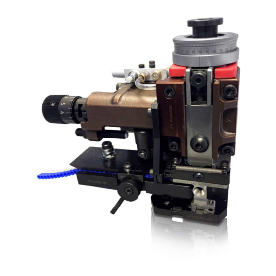
Page 14: Product Description
5.2 MAIN APPLICATIONS The primary application for the Uni-M ferrule appli- cators are crimping of insulated wire end ferrules in strip form to the end of pre-stripped wire. Operating Instructions | Version 1.0 (05-2018) | Uni-M Ferrule 14 | 32... -
Page 15: Definitions
Danger if operated by unqualified personnel! The Uni-M applicators must only be operated by qualified personnel. There are multiple areas on the Uni- M that are danger zones. Improper use or inadequate caution may result in injury to the operator or dam- age to the product. -
Page 16: Installation
Lift the lever (1) to lock the applicator into position. Firmly grasp the applicator and try to move it to ensure it is secure. Remove the red tooling protection ring (4). Operating Instructions | Version 1.0 (05-2018) | Uni-M Ferrule 16 | 32... -
Page 17: Air Connection
6.1.2.4 Activate split cycle mode The Uni-M ferrule applicator requires a split cycle process. Please refer to the press manual to enable split cy- cle processing. 6.1.2.4.1 Use on automatic wire processing machines When using automatic processing machines, split cycle operation and the use of the wire funnels is required. -
Page 18: Verify/Set Crimp Height Dials
15. The blade cuts through the insulation and the pusher blade (6) pushes the ferrule into the cavity (5) and hold it in place as seen in Fig. 3. Fig. 1 Fig. 2 Fig. 3 Operating Instructions | Version 1.0 (05-2018) | Uni-M Ferrule 18 | 32... -
Page 19: Verify/Adjust Crimp Height
Open the shield and clear the ferrule on the anvil if one is present. Lift the brake lever (1) and feed finger. Gently pull the ferrule strip to the left to remove the strip. Operating Instructions | Version 1.0 (05-2018) | Uni-M Ferrule 19 | 32... -
Page 20: Remove The Applicator
1.5 or more ferrules so that the entire range may be processed in the same applicator. As long as the forward stroke only advances one ferrule, then the backstroke position is not critical. Operating Instructions | Version 1.0 (05-2018) | Uni-M Ferrule 20 | 32... -
Page 21: Forward Stroke Adjustment
Slowly lower the press ram until the feed finger is completely pushed forward. The terminal should comes to rest over the insulation support as shown in Fig. 5. Fig. 5 Fig. 4 Operating Instructions | Version 1.0 (05-2018) | Uni-M Ferrule 21 | 32... -
Page 22: Feed Timing And Rate Adjustment
When the funnel is properly adjusted, it should not be possible to see the edges of the ferrule insulation when looking into the funnel. Funnels can be adjusted both horizontally and vertically. Incorrect Correct Operating Instructions | Version 1.0 (05-2018) | Uni-M Ferrule 22 | 32... -
Page 23: Maintenance
7.2 CUSTOMER SERVICE 7.2.1 Hotline We advise the customer in case of technical problems with the machine, to contact the local Schleuniger dis- tributor first, at „TSInbox@schleuniger.com”. Operating Instructions | Version 1.0 (05-2018) | Uni-M Ferrule 23 | 32... -
Page 24: Trouble Shooting Procedure
If problems occur, which cannot be solved by the help of this Manual, the Schleuniger distributor or the tech- nical staff of Schleuniger is ready to assist you. In such situations it is essential to provide a precise description of the matter. -
Page 25: Lubrication Of Components
NOTICE Spare tools! It is always recommended to have an additional set of crimping tools to prevent down time in case a piece is damaged. Operating Instructions | Version 1.0 (05-2018) | Uni-M Ferrule 25 | 32... - Page 26 Screw (12) secures the lower crimp anvil. • Remove the lower anvil(s) as needed. NOTICE Clean surfaces! Before replacing tooling kit parts, be sure that all surfaces are clean and free of debris. Operating Instructions | Version 1.0 (05-2018) | Uni-M Ferrule 26 | 32...
- Page 27 After installing the ram back into the applicator, ensure that the ram does not drop freely onto the crimp anvil(s). This may result in damage to the crimp dies. Whenever possible, the red protection collar should be installed to prevent tooling damage. Operating Instructions | Version 1.0 (05-2018) | Uni-M Ferrule 27 | 32...
-
Page 28: Spare Parts
20 – 22AWG I.D. = 0.09" (2.3mm) APM-K008701 18 AWG I.D. = 0.11" (2.8mm) APM-K008175 18- 16AWG I.D. = 0.13" (3.3mm) APM-K006667 14 AWG I.D. = 0.14" (3.6mm) APM-K008585 Operating Instructions | Version 1.0 (05-2018) | Uni-M Ferrule 28 | 32... -
Page 29: Decommissioning
Remove any parts that might be used on other applicators. 2. Pack in an appropriate container. For proper environmental safeguards, please send the press to an authorized waste disposal center. Operating Instructions | Version 1.0 (05-2018) | Uni-M Ferrule 29 | 32... -
Page 30: Appendix A: Panduit End Ferrule Specifications
Fig. 4 When using Panduit end ferrules, crimp height should be measured at the high spot (CH1) using standard micrometers. 10.3 CRIMP PARAMETERS AND SETTINGS FOR PANDUIT FERRULES Operating Instructions | Version 1.0 (05-2018) | Uni-M Ferrule 30 | 32... -
Page 31: Feed Adjustments Using The Panduit Adjustment Blocks
Turn the positioning knob (2) to re-position the terminal. Counterclockwise increases the feed and will move the terminal further to the right. Clockwise decreases the feed and will move the terminal further to the left. Operating Instructions | Version 1.0 (05-2018) | Uni-M Ferrule 31 | 32... - Page 32 12. The blade cuts through the insulation and the pusher blade (6) pushes the ferrule into the Fig. 1 cavity (5) and hold it in place as seen in Fig. 3. Fig. 2 Fig. 3 Operating Instructions | Version 1.0 (05-2018) | Uni-M Ferrule 32 | 32...
Need help?
Do you have a question about the Uni-M and is the answer not in the manual?
Questions and answers