Table of Contents
Advertisement
Quick Links
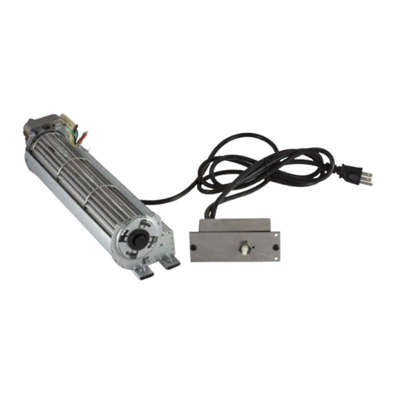
DA3610T THERMOSTATICALLY-
CONTROLLED BLOWER ACCESSORY
This blower kit is to be used only with BHDV, BDV, DDV, or HDV Series Vanguard Direct-Vent Fireplaces and SDV, SBV
series Vanguard B-Vent and Direct-Vent Freestanding Cast Iron Stove Burners.
Parts included with this kit:
Part No.
Description
103581-02
Blower with speed control and 6-foot cord.
104901-01
Wire
104902-01
Bracket
101378-01
Thermal Switch
103649-02
Mounting Hardware Kit (includes the following parts)
103650-01
Control Knob
103651-01
Lock Nut
M11084-38
#8 x 3/8" sheet metal screws
101629-01
Plastic Hole Bushings
104903-01
Wiring Diagram Decal
Tools Required
• Pliers
• Phillips Screwdriver
If any of these pieces are missing or damaged, or if the installation instructions for your fireplace or stove are not included in this
manual, contact the dealer where you purchased this kit or DESA International at 1-800-972-7879 for referral information.
®
Quantity
1
1
1
1
1
1
5
2
1
Advertisement
Table of Contents

Summary of Contents for Vanguard DA3610T
- Page 1 CONTROLLED BLOWER ACCESSORY INSTALLATION INSTRUCTIONS This blower kit is to be used only with BHDV, BDV, DDV, or HDV Series Vanguard Direct-Vent Fireplaces and SDV, SBV series Vanguard B-Vent and Direct-Vent Freestanding Cast Iron Stove Burners. Parts included with this kit: Part No.
- Page 2 Blower SWITCH are attached securely. Make sure the Thermal screw retaining the green wire is tight. Switch When installing the DA3610T thermostati- cally-controlled blower, you must first se- Thermal cure the thermal switch to the blower. Lower Rear Swith Remove the two hex head screws on the...
- Page 3 WARNING: Never touch the OPERATING THE BLOWER blower wheel while in operation. AND HDV The DA3610T thermostatically-controlled blower has an ON setting and an OFF set- Continued 10. Peel off the backing paper and stick the ting. The blower will only run when the supplied wiring diagram decal on the 8.
- Page 4 Follow all until tight against the side of rear cover. When installing the DA3610T thermostati- local codes. Place control knob provided onto shaft cally-controlled blower accessory, you must (see Figure 7).
- Page 5 Installation Instructions INSTALLING DA3610T BLOWER ACCESSORY IN Rear FREESTANDING Cover STOVE SERIES SDV AND SBV Continued INSTALLING REAR COVER Screw 1. Lift rear panel over vent pipe connec- tion on firebox. Rear cover will rest on the bottom ledge of the stove body.
- Page 6 104890 01 INTERNATIONAL NOT A UPC 2701 Industrial Drive, P.O. Box 90004 Bowling Green, KY 42102-9004 Technical Service Department 1-800-323-5190 Parts Department 1-800-972-7879 www.desatech.com 104890-01 REV. B 05/99...
Need help?
Do you have a question about the DA3610T and is the answer not in the manual?
Questions and answers