
Related Manuals for Nieaf-Smitt EazyAmpPLUS

Summary of Contents for Nieaf-Smitt EazyAmpPLUS
- Page 1 EazyAmp PLUS AC True RMS Stoomtang Multimeter AC True RMS Clamp Meter Handleiding / Manual...
- Page 2 I www.nieaf-smitt.com Helpdesk: E helpdesk.msbv@wabtec.com I www.nieaf-smitt.nl/support Nieaf-Smitt is a brand name of Wabtec N ET H ERL A ND S (c) Copyright 2020 All rights reserved. Nothing from this edition may be multiplied, or made public in any form or manner, either electronically, mechanically, by photocopying, recording, or in any manner, without prior written consent from Wabtec Netherlands B.V.
-
Page 3: Table Of Contents
Symbolen Inleiding en beschrijving Metingen AC (True RMS) stroom AC (True RMS)/DC spanning Lage Impedantie spanning Weerstand Continuïteit Capaciteit Diode Contactloze spanning (ncv) Mode en achtergrondverlichting 4.10 Max-Min knop 4.11 Gegevens bewaren en meetpuntverlichting 4.12 Automatische uitschakeling Onderhoud Specificaties www.nieaf-smitt.com... -
Page 4: Veiligheid
Stel de functieschakelaar in op de juiste positie voordat u meet. Bij het meten van spanning, niet overschakelen naar de stroom / weerstand stand. Meet de stroom niet op een circuit waarvan de spanning meer dan 1000 V bedraagt. www.nieaf-smitt.com... -
Page 5: Inleiding En Beschrijving
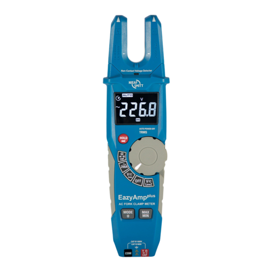
Indien de apparatuur wordt gebruikt op een wijze die niet door de fabrikant is gespecificeerd, kan de door de apparatuur geboden bescherming worden aangetast. Functie Maximale invoer 200 AAC VDC, VAC 1000 VAC/DC VDC, VAC (lage ingangsimpedantie) 600 VAC/DC Weerstand, Capaciteit, Diode test 300 VAC/DC www.nieaf-smitt.com... - Page 6 Contactloze spanningdetector (NCVD) Stroombek Contactloze spanningindicator LED LCD-scherm Draaischakelaar indicatie LED Knop Data Hold en verlichting Draaischakelaar Meetfuncties (met achtergrond verlichting) Max Min-knop 10. Mode en achtergrondverlichting 11. V Ω CAP · ))) aansluiting 12. COM-aansluiting 13. Batterijkap (achterkant) www.nieaf-smitt.com...
-
Page 7: Metingen
Stel de functieschakelaar in op de uitpositie wanneer de meter niet in gebruik is. AC (True RMS) stroom WAARSCHUWING: Zorg ervoor dat de testkabels van de meter worden losge- koppeld voordat de stroommeting wordt uitgevoerd. www.nieaf-smitt.com... -
Page 8: Ac (True Rms)/Dc Spanning
Door de capacitieve koppeling tussen de draden lijkt alsof de niet-aangesloten draden zijn aangesloten op een echte spannings- bron. Met de Low Z-instelling zal er een belasting op het circuit worden aangesloten waardoor de spookspanning sterk vermindert. www.nieaf-smitt.com... -
Page 9: Weerstand
Sluit de snoeren aan op het te testen circuit Lees de spanning op het LCD-scherm Weerstand Zet de functieschakelaar op de ‘Ω cap’ positie Gebruik de mode knop om de weerstandsmeting te www.nieaf-smitt.com... -
Page 10: Continuïteit
Verbind de testsnoeren met het te testen circuit of onderdeel Als de weerstand minder dan 50 is, zal een geluid klinken Ω Capaciteit WAARSCHUWING: Om elektrische schokken te voorkomen, moet de conden- sator die wordt getest worden ontladen voor de meting. www.nieaf-smitt.com... -
Page 11: Diode
Houd de bovenzijde van de meter dicht bij de spanningsbron Als er spanning aanwezig is, zal de rode LED lang branden LET OP: Raak de bovenkant van de meter niet aan bij het gebruik van deze function. Test op een bekend circuit voor gebruik. www.nieaf-smitt.com... -
Page 12: Mode En Achtergrondverlichting
Verwijder de batterij als de meter 60 dagen of langer niet word gebruikt, en sla deze apart op. Battery vervangen Verwijder de schroef van het batterijklepje Open het batterijcompartiment Vervang de 1.5 V*2 AA batterijen Zet de batterijklepje weer vast www.nieaf-smitt.com... -
Page 13: Specificaties
+ (1.0 % + 2 d) 1000 V + (1.2 % + 2 d) Invoer impedantie: 10 MΩ Lage ingang Impedantie (low Z): 3 kΩ MAX 600 V DC Nauwkeurigheid vanaf +3.0 % van aflezing +5 digits Overspanningsbeveiliging: 1000 V www.nieaf-smitt.com... - Page 14 Overrange bescherming: 300 V rms Functie Testconditie Reading Diode Teststroom: 1.5 mA; Voorwaartse diode Open circuit spanning spanningsverlies < 3 VDC typisch Continuïteit Teststroom < 0.35 mA Zoemer maakt een lang geluid, indien de weerstand <50 Ω Overrange bescherming: 300 V rms www.nieaf-smitt.com...
- Page 15 Symbols Introduction and description Measurements AC (True RMS) current AC (True RMS)/DC voltage Low Z voltage Resistance Continuity Capacitance Diode Non-Contact Voltage (ncv) Mode en backlight 4.10 Max-Min 4.11 Data hold and flashlicht 4.12 Auto power off Maintenance Specifications www.nieaf-smitt.com...
-
Page 16: Safety
Remove the battery if meter is to be stored for longer than 60 days. Warning Set function switch to the appropriate position before measuring. When measuring volts do not switch to current/ resistance modes. Do not measure current on a circuit whose voltage exceeds 1000 V. www.nieaf-smitt.com... - Page 17 If the equipment is used in a manner not specified by the manufacturer, the protection provided by the equipment may be impaired. Maximum input Function 200 AAC VDC, VAC 1000 VAC/DC VDC, VAC (low imput impedance) 600 VAC/DC Resistance, Capacitance, Diode test 300 VAC/DC www.nieaf-smitt.com...
-
Page 18: Introduction And Description
Non-contact AC voltage indicator light Negativity LCD display Knob indicator light Data Hold and Flashlight button Rotary function switch Rotary backlight Max-Min button 10. Mode and backlight 11. V ΩCAP ·))) jack 12. COM input jack 13. Battery Cover www.nieaf-smitt.com... - Page 19 Auto range mode Direct current/voltage Alternating voltage and current Low battery indicator Volts (voltage) Ohms (resistance) Amperes (current) n, m, W , M, k Unit of measure prefixes: nano, milli, micro, mega en kilo · ))) Continuity test Diode test www.nieaf-smitt.com...
-
Page 20: Measurements
Set the function switch to the ‘~200 A’ position Place the current fork in the middle of one wire of the cable (Phase or Neutral) The clamp meter LCD will display the reading AC (True RMS ) / DC voltage www.nieaf-smitt.com... -
Page 21: Low Z Voltage
If measuring DC voltage, touch the red test lead to the positive side of the circuit and the black test lead to the negative side of the circuit Connect the test leads to the circuit under test Read the voltage on the LCD display www.nieaf-smitt.com... -
Page 22: Resistance
Use the Mode button to select resistance measurement Insert the black test lead into the COM terminal and the test lead into the V terminal Connect the test probe tips across the circuit or component under test. Read the resistance on the LCD display Continuity www.nieaf-smitt.com... -
Page 23: Capacitance
Connect the test probe tips across the circuit or component under test Read the value on the LCD display The display will indicate the proper decimal point and value For high capacitance values the measurement can take several minutes before the final reading stabilizes www.nieaf-smitt.com... -
Page 24: Diode
Do not touch the top of the meter when using this function. Test on known live circuit before using. Mode en backlight To enable / disable backlight of the function buttons, press Mode for over 1 second to turn the button backlight on or off. www.nieaf-smitt.com... -
Page 25: Max-Min
If the meter is not to be used for 60 days or more, remove the battery and store it separately. Battery replacement Remove the Phillips head screw that secures the rear battery door Open the battery compartment Replace the 1.5V*2 AA batteries Secure the battery compartment www.nieaf-smitt.com... -
Page 26: Specifications
Weight 230 g Safety For indoor use and in accordance with the requirements for double insulation to EN 61010-1;: EN 61010-2-030; EN 61010-2- 032; EN 61010-2-033 Overvoltage CAT IV 600 V / CAT III 1000 V, Pollution Degree 2. www.nieaf-smitt.com... - Page 27 + (1.5 % + 4 d) 100 Ω 600.0.0 kΩ + (1.5 % + 4 d) 6.000 MΩ 1 kΩ + (2.5 % + 4 d) 60.00 MΩ 10 kΩ + (3.5 % + 4 d) Overrange protection: 300 V rms www.nieaf-smitt.com...
- Page 28 Test current of 1.5 mA Forward voltage typical; Open circuit voltage drop of diode < 3 VDC typical Continuïteit Test current < 0.35 mA Buzzer makes a long sound, while resistance is <50 Ω Overrange protection: 300 V rms www.nieaf-smitt.com...
Need help?
Do you have a question about the EazyAmpPLUS and is the answer not in the manual?
Questions and answers