Table of Contents
Advertisement
Quick Links
160623A03-1
SW830-2
INSTALLATION
It is essential to install the unit properly to ensure safe and reliable operation. Please read through all
instructions thoroughly and carefully before installing the unit. The correct mounting and wiring is the
key to the effectiveness of SW830-2 switch. Installers must read and follow installation instructions and
warnings in the manual from original manufacturer. The vehicle operator should verify this system is
fastened to the vehicle securely and is functioning properly. Failure to follow all safety precautions and
instructions may void warranties, cause personal injury and/or vehicle damage, including fire.
MOUNTING
Assemble the included panel stand and secure it onto a desired smooth surface via suction cup, where it can be easily accessed by the vehicle
operator. If no smooth surface is present, use the included adhesive base to assist the mounting; ensure that the surface is cleaned thoroughly
before applying the adhesive base onto the mounting surface. Once the mounting stand is fitted, secure the control panel tightly onto the stand.
WARNING:
Do not interfere with the proper operation of the vehicle airbag deployment system.
WIRING
Use wires that are capable of handling the required current. Route the wires
properly to prevent wear, overheating and interference with air bag deployment.
Ensure that all connections are tight and double check wiring before connecting
to the vehicle battery.
SW1, SW2, SW3, SW4 : +VDC Output Connections,
each connects to one auxiliary device / relay / input up to 0.1 Amps max.
SW5, SW6, SW7 : +VDC Output Connections,
each connects to one auxiliary device / relay / input up to 0.2 Amps max.
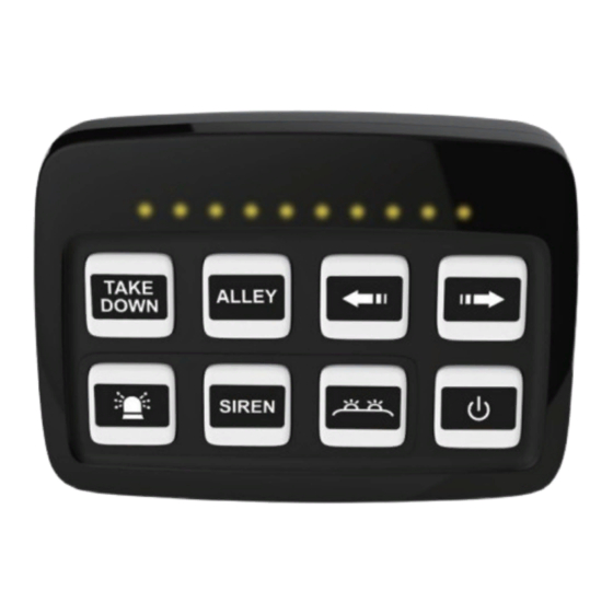
CONTROL PANEL / FUNCTION
Button B5:
Activates SW5 Connection; may be set as an ON/OFF or a momen-
tary switch.
This button may be configured to turn Button B7 ON or OFF upon
activation or deactivation. (Button Mapping, see "PROGRAMMING"
section for more details)
This button may be configured to turn Button B6 OFF when deacti-
vated and turn itself ON when Button B6 is activated. (European
Siren Interlock, see "PROGRAMMING" section for more details)
Multi-purpose Switch /
Control Panel
BLACK ...... -GND
RED ...........
YELLOW
ORANGE
PURPLE
Signal Display / LED Indicator:
Displays the flash signal or traffic director signal when
connected to a compatible lightbar, or directional/warning advisor.
Button B1, B2, B3, B4:
Activates SW1, SW2, SW3 or SW4 Connection respectively; each may be
set as an ON/OFF or a momentary switch.
Button B8:
Activates pre-programmed buttons. (Programmable Combo Button, See
"PROGRAMMING" section for more details)
Press and hold for 3 seconds to turn off all activated buttons, or press and
hold for 5 seconds to turn and the unit completely OFF.
While the unit is OFF, press and hold for 3 seconds to turn the unit back
ON.
Button B7:
Activates SW7 Connection; may be set as an ON/OFF or a momentary
switch.
This button may be configured to map with Button B5 to be turn ON or OFF
by Button B5. (Button Mapping, see "PROGRAMMING" section for more
details)
Button B6:
Activates SW6 Connection; may be set as an ON/OFF or a momentary
switch.
This button may be configured to turn Button B5 ON when activated and
turn itself OFF when Button B5 is deactivated. (European Siren Interlock,
see "PROGRAMMING" section for more details)
Control Panel
GREEN
......
+VDC
BLUE
.........
.....
SW1
BROWN .....
.....
SW2
GRAY .........
......
SW3
WHITE
........ LED Display Signal
SW4
SW5
SW6
SW7
WHITE
input wire is
Advertisement
Table of Contents

Related Manuals for Cell2 SW830-2

Summary of Contents for Cell2 SW830-2
- Page 1 The correct mounting and wiring is the key to the effectiveness of SW830-2 switch. Installers must read and follow installation instructions and warnings in the manual from original manufacturer. The vehicle operator should verify this system is fastened to the vehicle securely and is functioning properly.
- Page 2 PROGRAMMING Programmable Combo Button: Button B8 may be used to activate pre-programmed buttons from Button B1 to to B7. To set-up pre-programmed buttons: 1. Press and hold for 3 seconds to enter PROGRAMMING MODE. Top Left LED Indicator x4 will light to indicate that you are in PROGRAMMING MODE. 2.
Need help?
Do you have a question about the SW830-2 and is the answer not in the manual?
Questions and answers